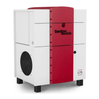
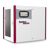
This document describes the CompAir L90 - L132 V4, L90e - L132e V4, and L90RS - L132RS V4 series of screw compressors, providing operating instructions, technical specifications, usage, and maintenance information.
Function Description
The CompAir screw compressors are oil-lubricated, single-stage units designed for compressing air. The compression stages consist of a main rotor and an auxiliary rotor with intermeshing spiral toothing. Compression chambers are delimited by the flanks of the toothing and the compressor casing. The rotation of the rotors continuously reduces the volume in the chambers until the compressed air is pushed out through the outlet window of the stage casing. These screw compressors operate without oscillating masses, but with a pulsing output.
The main components of the electronic control unit are a microprocessor, a touchscreen, film-protected keys, and LEDs. This unit manages the compressor's operation, including starting, stopping, and monitoring various parameters.
The air circuit involves drawing in air through a suction filter and regulating it via a suction regulator. The air then enters the screw compressor, where it is mixed with injected oil for lubrication and cooling. The compressed air-oil mixture passes through a fine separator, where oil is removed. The compressed air then flows through an aftercooler before being discharged.
The oil circuit involves oil being injected into the compressor stage for lubrication, sealing, and cooling. The oil flows from the pressure vessel through an oil filter and then into the screw compressor. After compression, the oil is separated from the air in the fine separator and then cooled in an oil cooler before being recirculated.
Important Technical Specifications
The compressors are available in both air-cooled ("A") and water-cooled ("W") versions, and in 50Hz and 60Hz frequencies.
Operating Pressure:
- Maximum operating pressure: 7.5 to 13 bar (depending on model and configuration).
- Minimum operating pressure: 5.0 bar.
Ambient Temperature:
Volume Flow (at 7.5 bar discharge pressure):
- L90/L90e (50Hz, air-cooled): 18.16 m³/min
- L90/L90e (50Hz, water-cooled): 18.16 m³/min
- L110/L110e (50Hz, air-cooled): 21.6 m³/min
- L110/L110e (50Hz, water-cooled): 21.6 m³/min
- L132/L132e (50Hz, air-cooled): 24.45 m³/min
- L132/L132e (50Hz, water-cooled): 24.45 m³/min
- L90RS (50Hz/60Hz, air-cooled): 5.27 to 18.08 m³/min (variable speed)
- L110RS (50Hz/60Hz, air-cooled): 5.27 to 21.46 m³/min (variable speed)
- L132RS (50Hz/60Hz, air-cooled): 5.27 to 24.34 m³/min (variable speed)
Sound Pressure Level (ISO 2151):
- Typically between 72 and 78 dB(A), depending on the model and configuration.
Rated Power of Drive Motor:
- L90/L90e: 90 kW
- L110/L110e: 110 kW
- L132/L132e: 132 kW
Total Oil Quantity:
Dimensions (L x W x H):
Cooling Water Specifications (for water-cooled models):
- Cooling water inlet temperature: min. 5 / max. 35 °C.
- Cooling water outlet temperature: max. 55 °C.
- Cooling water pressure: max. 10 bar.
- Cooling water connections: EN 10226-1 Rp 1 1/4 (DIN 2999-R 1 1/2).
- Cooling water quantity: 90 to 170 l/min (depending on model and ΔT).
Usage Features
The compressor is designed for continuous operation and can be started automatically. The electronic control unit provides a user-friendly interface with a touchscreen display, start/stop buttons, and LEDs indicating operational status (green LED for system in operation, flashing yellow for warning/maintenance, red for fault).
Safety Features:
- Emergency-stop button for immediate shutdown.
- Protective covers and enclosures for moving parts and electrical components.
- Safety signs are prominently displayed to warn against hazards such as electrical shock, hot surfaces, suspended loads, moving parts, hand injuries, automatic start-up, suffocation, crushing hazards, and industrial trucks.
- Specific safety signs indicate pressurized parts, the need to wear ear defenders, and warnings against working on electrical systems.
Transport and Positioning:
- The compressor is delivered on a transport pallet and packaged with a film cover.
- Lifting points are marked on the packaging and the compressor itself.
- Special care must be taken during transport to avoid tipping and ensure adequate forklift length.
- The compressor must be placed on an even, suitable substrate capable of bearing its weight (up to 2,800 kg).
- Adequate ventilation of the compressor room is crucial, with minimum channel cross-sections recommended for cooling air flow.
Commissioning and Operation:
- Before initial commissioning, a thorough inspection of the compressor and electrical connections is required.
- The drive motor rotational direction must be checked.
- The compressor can operate in "Ready to Start" (stand-by) or "On-Load" (operating under load) modes.
- The electronic control unit displays operational status and any fault messages.
Maintenance Features
Regular maintenance is essential for ensuring the longevity and efficient operation of the compressor. A detailed maintenance plan is provided, with tasks scheduled at various intervals:
Every 8 Operating Hours:
- Oil tank level check (check and refill if necessary).
- On-load/off-load machine function check.
- Pressure and temperature at discharge check.
- Control Panel check for fault messages.
Every 125 Operating Hours:
- Cooler/fan cleaning.
- Oil tank drain condensate.
Service Interval A (Every 2000 Hours, but no less than annually):
- Filter mats cooling air inlet (check, clean, and replace as necessary).
- Air filter (replace).
- Oil filter (replace).
- Condensate drain (aftercooler, function check).
- Electronic control unit (check for displayed maintenance requirements).
Service Interval B (Every 4000 Hours, but no less than annually):
- Customer operations log (check and adhere to operating parameters).
- Electronic control unit (check fault statistics).
- General maintenance/cleaning.
- Oil fine separator (replace).
- Switch cabinet cooling air inlet filter (replace).
- Frequency converter cooling air inlet filter (RS models) (replace).
- Moisture sensor replacement filter cap (RS models) (replace).
- Motor bearing lubrication (replace LC unit cartridge/grease cartridge).
- Safety valve (function test at least once a year).
- Hoses and pipelines (check for leaks or damage).
- Electrical wiring (check connections and condition).
- Compressor (maintain the compressor room and surroundings clean).
Service Interval C (Every 8000 Hours, but at least every two years):
- Pressure-retaining valve (replace).
- Suction regulator non-return valve (replace).
- Suction regulator pressure regulator (replace).
- Blow-off valve diaphragm (replace).
Inspections:
- Every 4 years: Electrical installation inspected by an electrician.
- Every 5 years: Internal inspection of the pressure vessel by a competent individual.
- Every 10 years: Strength test of the pressure vessel by an appointed body.
Specific Maintenance Procedures:
- Filter Mats: Inspect weekly/daily for dust accumulation and replace if defective.
- Oil Change: Drain used oil completely and refill with new, specified lubricant. The oil filter should also be replaced.
- Oil Filter: Replace filter elements when indicated by the electronic control unit.
- Fine Separator: Replace the oil fine separator when indicated by the electronic control unit.
- Air Filter: Replace the air filter element regularly.
- Moisture Sensor Protective Cap: Replace every 4000 operating hours.
- Grease Cartridge: Replace the grease cartridge when indicated by the control unit.
Troubleshooting:
The manual includes a comprehensive troubleshooting guide for various faults, such as the system not starting, the system remaining stationary during start-up, the system not reaching the set line pressure, system switches off, off-load pressure too high, oil in the air filter, and safety valve opens. Each fault is accompanied by possible causes and remedies.
Lubricants and Additives:
Only specified lubricants (FLUIDFORCE SCREW WARRANTY LUBRICANT) should be used. Safety data sheets for lubricants and additives must be observed.
Disposal:
The compressor and its components must be disposed of according to local and national regulations. Materials such as metals, cables, seals, plastics, filters, and operating fluids have specific disposal types (recycling, landfill, hazardous waste).