Models 5843, 5844, 5843S and 5844S
RS232 or TTL
1-
8
1
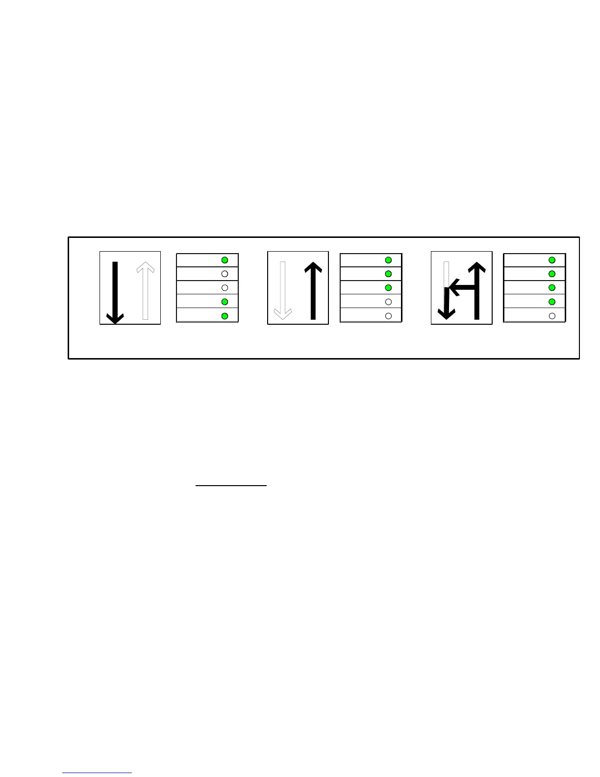
.2.9 Diagnostic LEDs
Each Link/Repeater is equipped with four diagnostic LEDs. They represent the electrical transmit (TE),
optic
al transmit (TO), electrical delivery (RE), and optical receive (RO) paths. These LEDs, when
illuminated, show that the appropriate path is active. When the Link/Repeater is transmitting, both TE
and TO LEDs will illuminate to show the transmit path active. When the Link/Repeater is receiving light
signals, both RO and RE LEDs will illuminate. If the unit is in the repeat mode and receiving light, the
RO, RE and TO LEDs will illuminate because the signal is being re-transmitted out the optical port, as
well as, being delivered to the D-connector. LEDs only illuminate when the path is active; powering of
the unit does not illuminate the LEDs unless their path is active. When data is present on the paths, the
LEDs may "flicker"; this is normal. The diagnostic LEDs may be used for trouble shooting by observing
that the illumination of the LEDs corresponds with activity in the unit. See Figure 5 for LED patterns and
signal paths.
Normal Repeat
PWR
RO
RE
OT
ET
23
Normal Receive
PWR
RO
RE
OT
ET
23
Normal Transmission
23
PWR
RO
RE
OT
ET
FIGURE 5. Diagnostic LED patterns and signal paths
NOTE
The LEDs only illuminate when there is signal traffic and are not illuminated during signal "quiet" times.
The LEDs may "flicker". This is normal operation.
1.2.10 Power Connections
1.2.10.1 Powering Model 5843HRT
Model 5843HRT may be powered either through pin 9+ (and pin 5-) of the 9 Pin D-
c
onnector or the external connector located on the back of the unit:
1) When powering the 5843HRT via pin 9 of its D-connector, the IED must supply
at
leas
t 250 mA (340mA for the 5843SHRT). The voltage should be regulated and wi
thin
a r
ange of 9 to 15 Vdc.
2) When powering the 5843HRT via its external connector, DYMEC offers a 110 Vac
to
12 Vdc
adapter (Model 4310S) that is designed specifically to plug into this connector.
Model 4310S assures reliable power over the temperature range of
0°C to + 70°C.