Do you have a question about the Garland P1GCCAS and is the answer not in the manual?
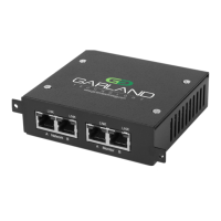
Details the function and status of LEDs for different ports on the front panel.
Defines the switch settings for various speed and tap modes.
Assigns ports to network and monitor interfaces in Breakout mode.
Assigns ports to network and monitor interfaces in Aggregate mode.
Assigns ports to traffic input and span interfaces in Span mode.
Step-by-step guide for installing the network TAP into a rack.
Guidance on using DIP switches to configure the operating mode.
Instructions for connecting network cables and power supply.
Details supported SFPs for copper, SM fiber, and MM fiber.
Contact information for technical support and inquiries.
This document describes the Garland Technology AggregatorTAP P1GCxAS / P1GCSAS, a portable network TAP series designed for monitoring copper network segments.
The P1GCxAS / P1GCSAS series TAPs are designed to provide non-intrusive access to network traffic for monitoring purposes. They allow network administrators to observe data flowing through a copper 10/100/1000MB network segment without affecting network performance or introducing points of failure. The P1GCSAS model specifically utilizes Small Form-Factor Pluggable (SFP) modules for its monitor ports, offering flexibility to use either copper or fiber SFPs depending on the monitoring tool's interface requirements. This innovative design facilitates easy installation into existing network infrastructure.
| Brand | Garland |
|---|---|
| Model | P1GCCAS |
| Category | Network Hardware |
| Language | English |