Tools Needed
• Drill and 3.2 mm (
1
/
8
in.) drill bit
• 8 and 10 mm wrenches
• 10 mm socket
• Metal saw appropriate for cutting a threaded rod
• #2 Phillips screwdriver
• Tape measure
• Pencil or marker
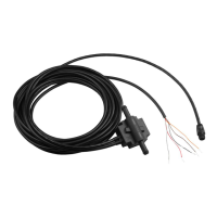
• Extension cables, if necessary (Connection Considerations, page4)
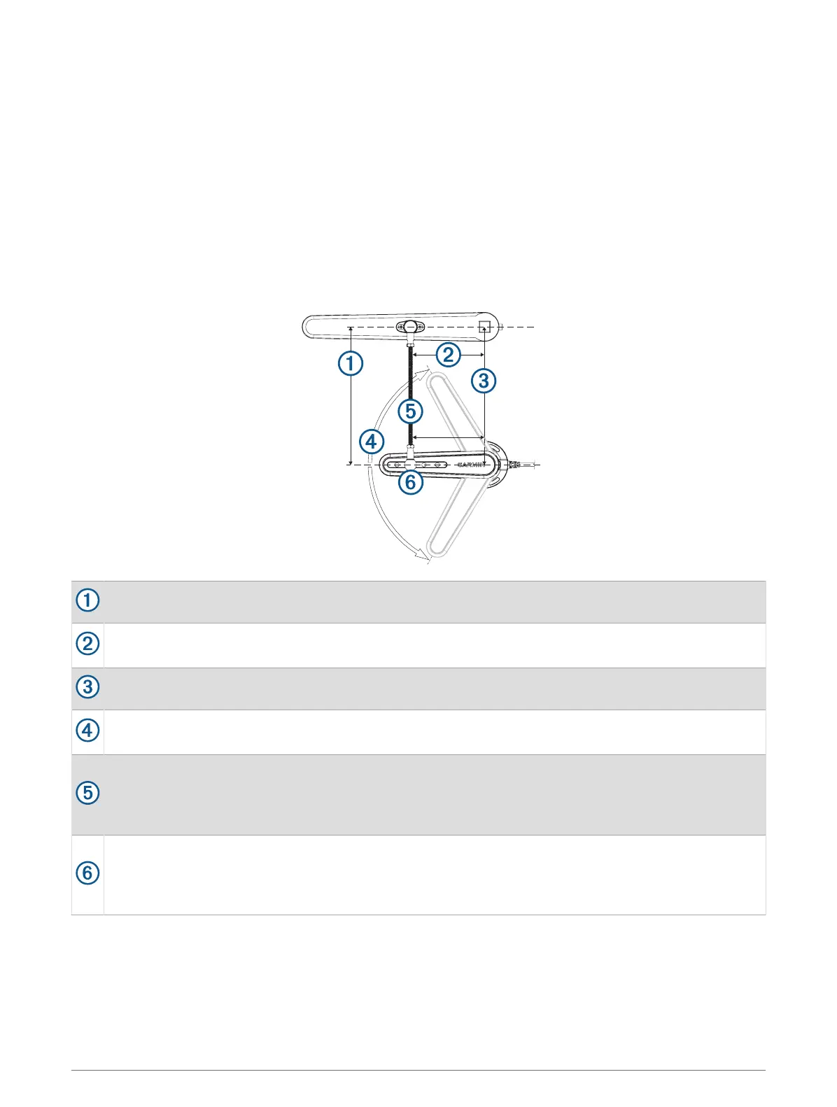
Mounting Considerations
The sensor must be installed parallel to the tiller arm while the rudder is amidships.
The distance from the rotation axis of the tiller to the ball-joint assembly must be the same as the
distance from the rotation axis of the sensor to the ball-joint assembly.
The sensor and rudder rotation axes must be aligned.
The maximum range of travel from stop to stop is 140 degrees (70 degrees from the center position to
each stop). Exceeding this range may cause damage to the sensor.
The rod that connects the sensor to the tiller arm is 300 mm (11.8 in.) long, and can be shortened if
needed.
The rod should be level when connected to the sensor and rudder. If a perfectly level installation is not
possible, the rod must be installed within +/- 5 degrees of level to function correctly.
The rod should be installed perpendicular to the tiller arm and sensor, using the second hole from the tip
of the sensor for the ball-joint connector.
Although the second hole is preferred, the other holes may be used if necessary, based on the installation
location.
Installation Instructions 3