Connection Considerations
• This sensor can be connected to a compatible Garmin
®
autopilot system with a 12-pin rudder feedback
connector.
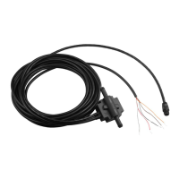
• The cable connected to the sensor is 78 in. (2 m) long.
◦ If needed, extension cables for the sensor are available from your Garmin dealer.
◦ Do not cut the sensor cable to extend or shorten it.
Installation Procedures
Installing the Sensor
For the best results, keep the rudder amidships during the sensor-installation process.
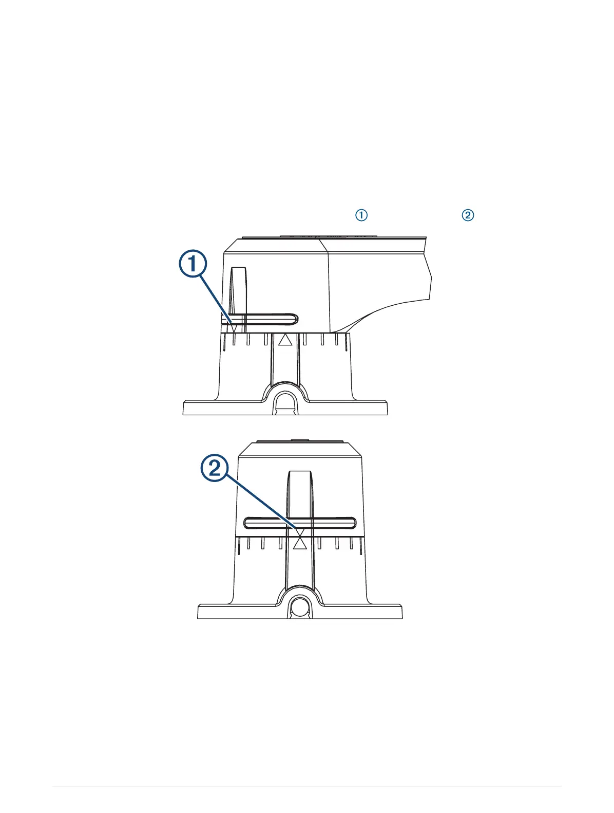
1 Rotate the sensor counter-clockwise so the arrows on the back line up in the center .
2 Place the sensor at the selected mounting location, and mark the center of the three mounting holes.
3 Place the tiller-arm mount on the tiller arm at the mounting location, and mark the center of the two
mounting holes.
4 Using a 3.2 mm (
1
/
8
in.) bit, drill three pilot holes in the mounting surface for the sensor, and two pilot holes
in the tiller arm for the tiller-arm mount.
5 Fasten one of the ball-joint assemblies to the tiller-arm mount using the included M6 locknut.
6 Place the other ball-joint assembly into the appropriate hole on the sensor (typically the second hole from the
tip), and fasten it with the included washer and locknut using a 10 mm socket.
4 Installation Instructions