Our policy is one of continue research and development in the quest to improve our products. We therefore reserve the rights to amend information provided in this
document, without notice.
For sales or technical support please contact Irri-Gator Products (Pty) Ltd at: Tel: +27 21 9827561, Fax: +27 21 9814473, E-mail: info@irrigator.co.za
P. O. Box 889, Brackenfell, 7561, Western Cape Province, South Africa
The output wire loom format as shown in Figure 6 below
Figure 6
It is advisable to locate the output devices to be switched by the radio receiver module, such as solenoids and
relays, as close to the receiver module as is practically possible. These output devices are activated with a short
DC pulse signal and long cable/wire run lengths between the output device and the radio receiver module can
be problematic (can cause intermittent operation).
We do not suggest that you exceed 5m in total cable/wire length between the radio receiver module and the
output device to be controlled. Use a wire size of 1.5mm² if you intend to locate the output device/s away from
the receiver module up to 5m away.
The Gator G4.0 radio receiver module uses a two wire 12VDC pulse signal of 60mSec in length. Compatible
output devices should be selected to meet this specification and tested properly for reliable use with the radio
receiver module. Consult with Irri-Gator Products for a list of approved devices.
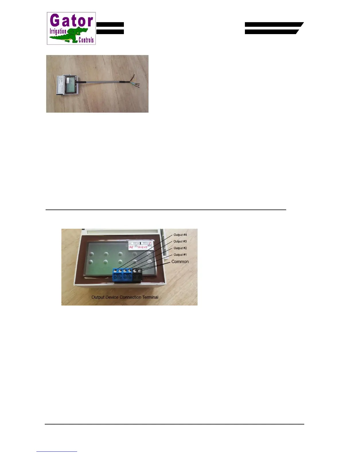
Connecting the output devices to the G4.0 receiver module equipped with the plug connection format
This version of the G4 radio receiver module is equipped with a 6 terminal pins and a plug (black and
blue) as shown in Figure 7 below.
Figure 7
Looking from the rear (the mounting slot end) of the radio receiver module the terminals are as follows –
Terminal 1 – Common (Black)
Terminal 2 – Common (Black)
Terminal 3 – Output #1 (Blue)
Terminal 4 – Output #2 (Blue)
Terminal 5 – Output #3 (Blue)
Terminal 6 – Output #4 (Blue)
Figure 8 below shows two solenoid valves that have wire to the radio receiver modules terminal plug. The
green wire (plus) from solenoid valve #1 is wired to the first blue terminal (terminal 3 being the closest
blue terminal to the black terminals). The green wire (plus) from solenoid valve #2 is wired to the second
blue terminal (terminal 4). The black wires (minus) are wired to the black terminals in no specific order.
 Loading...