6
3.2 Check Condition of Internal Battery
Before making resistance or continuity tests, check the
condition of the internal battery. First turn the function/range
switch to the ohms Rx1 position. Short the test leads together
and the needle indicator should deflect to the right side of the
scale. Keep the test leads shorted together while
simultaneously turning the zero ohms adjustment dial until the
needle indicates zero at the right side of the ohms scale. If the
needle will not zero, replace the batteries with two new 1.5 volt
AA size batteries (see Battery Replacement).
1) Fully seat the test leads in the correct input jacks, (-) black
lead, (+) red lead.
5
1) Set the function/range switch to the proper position
before making a measurement. When the voltage or
current is not known, it MUST be determined that the
capacity of the selected range will handle the amount of
voltage or current in the circuit (see #3 under “For Your
Safety”). Always start with the highest range in the
function. If the voltage applied falls within the range of
a lower setting, reset the function/range switch to the
appropriate setting for greatest accuracy of reading.
2) Avoid placing the tester in areas where vibration, dust or
dirt are present. Do not store the tester in excessively
hot, humid or damp places. This tester is a sensitive
measuring device and should be treated with the same
regard as other electrical and electronic devices.
3) Using the tester in areas with high magnetic fields can
result in inaccurate readings. For greatest accuracy of
reading, lay the tester on a flat, non-metallic surface.
4) When the tester is not in use, keep the function/range
switch in the OFF position. This keeps the needle
indicator from deflecting or “bouncing” excessively.
5) When disconnecting the test leads from the unit, always
grasp the leads where the input jacks meet the tester
housing. Never pull the leads out of the jacks by the
insulated wire or transport the tester using the test leads
as a carrying strap.
6) Never immerse the tester in water or solvents. To clean
the housing use a damp cloth with a minimal amount of
mild soap.
7) If the resistance (ohms) function of the tester is not going
to be used for a week or more, remove the internal
battery to avoid potential leaks that may damage the unit.
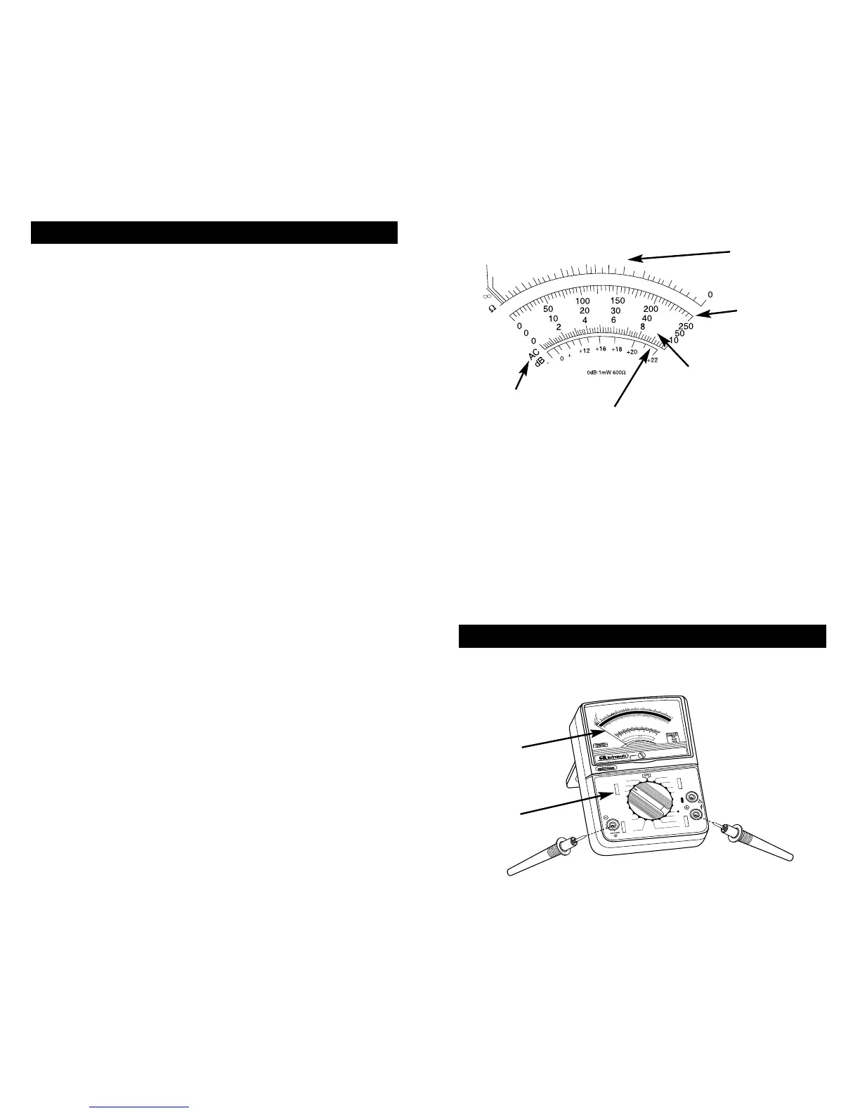
3.1 Preliminary Adjustments
Fully seat the test leads in the correct input jacks. If
necessary, using a small flat tip screwdriver, slowly turn the
mechanical zero adjustment screw clockwise or counter-
clockwise until the needle indicator is directly over the three
black zeros at the left end of the scale.