14
scale. If the needle will not zero, replace the internal
batteries with two new 1.5 volt AA size batteries (see
Battery Replacement) .
3) Touch the test leads to the resistance or non-energized
circuit to be measured. Measure the value of the reading
on the ohms scale and multiply the reading by 1000. If
you’re making basic continuity tests, the needle indicator
should move all the way to the right side of the ohms
scale if continuity exists.
Note: When switching the unit back and forth from ohms to
other functions, always zero the needle indicator before
taking another reading. Failure to zero the needle before
taking resistance/continuity measurements will result in
inaccurate readings.
Continuity Buzzer Setting
For quick, audible continuity checks, turn the function/range
switch to the setting. If the circuit under test has a
resistance of 100 ohms or less, the internal buzzer will sound
when the test leads are touched to the circuit. This makes
continuity checks quick and easy. Note: The needle indicator
will not indicate resistance values when the tester is in the
mode. Do not operate the continuity buzzer continuously
as this will discharge the internal batteries.
13
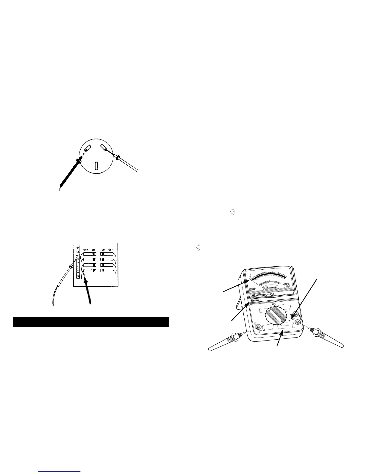
6.2 Appliance Receptacles
Set the function/range switch to 250 VAC. Touch the test
leads to the receptacle slots. The tester should read 240 VAC
between the two “hot” sides of the receptacle, and 120 VAC
between the neutral slot and either of the two “hot” sides
(see fig. 7).
6.3 Circuit Breaker Panel
To test for defective circuit breakers, set the function/range
switch to the 250 VAC or 600 VAC settings. Touch one test lead
to the neutral (buss) terminal strip of the breaker panel and the
other test lead to the terminal on the circuit breaker (see fig. 8).
The tester should read 120 VAC on the 0-250 scale.
For resistance and circuit continuity testing with power OFF
1) Fully seat the test leads in the input jacks.
2) Set the function/range switch to the Rx1K position and
short the test leads together. Using the zero ohms
adjustment dial, slowly turn the dial until the needle
indicator reads -0- ohms at the right end of the ohms
Figure 7
Figure 8
7.0 Resistance/Continuity Measurement