POWER
1
2
3
4
5
LAN
RESET
2
BELL
ON=5S
OFF=1S
1
+
-
*
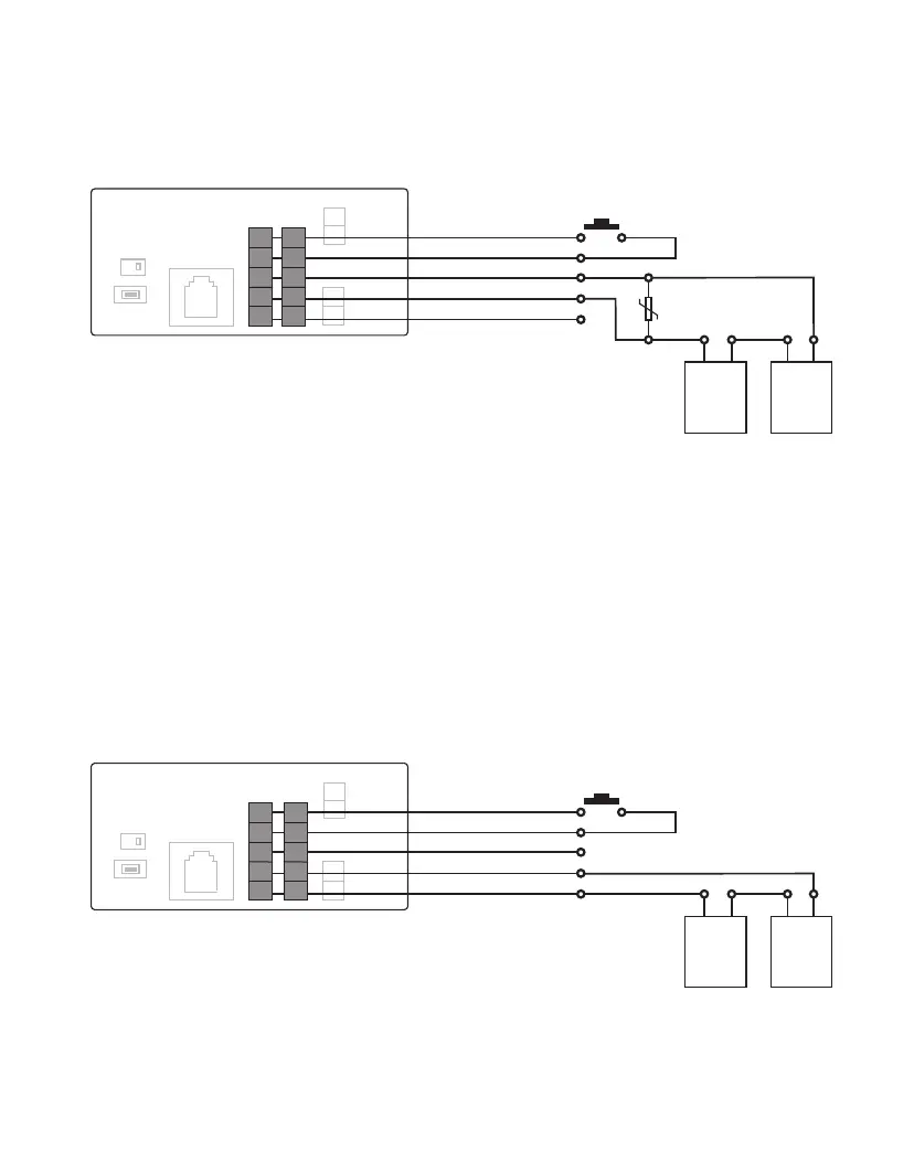
Red
Black
Green(NormallyOpen)
Blue(Common)
Brown(NormallyClosed)
PushtoExitButton(optional)
Varistor
(MOV)
Lock
Power
Supply
Electronic
Lock
POWER
1
2
3
4
5
LAN
RESET
2
BELL
ON=5S
OFF=1S
1
+
-
*
Red
Black
Green(NormallyOpen)
Blue(Common)
Brown(NormallyClosed)
PushtoExitButton(optional)
Lock
Power
Supply
Electronic
Lock
Wiring Diagram for Normally Closed Circuit
(e.g. Electronic Mag Lock)
Wiring Diagram for Normally Open Circuit
(e.g. Electronic Door Strike or Deadbolt)
1
2
3
4
5
1
2
3
4
5
6
PL963M/PMLockandBellRelaysareRatedMaximum3Ampsat250VACor30VDC
Please be advised that LOCK1 could be triggered by APP and Access Codes,
but LOCK2 could be triggered ONLY by APP, not Access Codes.
If you only use this system for one Door, please connect LOCK1 for your application.
LOCK1
LOCK2
LOCK1
LOCK2
PL963M/PMLockandBellRelaysareRatedMaximum3Ampsat250VACor30VDC
Please use LOCK1 for your gate control connection if this system is for controlling one door/ gate
 Loading...