Do you have a question about the GDS 202 and is the answer not in the manual?
Configuration options for zone signal selectors on the control unit.
Details on pre-alarm, full alarm, and fault alarm relays and their specifications.
Specifications including relay inhibit, remote reset, protection, weight, and dimensions.
Details on control unit power supply, output, consumption, and indicator LEDs.
Information on sensor cable, alarm relays, and relay inhibit/reset functions.
Specifications for the F200 component including power, consumption, and indicators.
Specifications for F200 (Flammable), T200 (Toxic), and R200 (Refrigerant) sensors.
Describes system behavior during stabilization, pre-alarm, and full alarm conditions.
Illustrates common configurations for connecting 3-wire sensors.
Guidelines for mounting the control unit, including location and mains supply.
Recommendations for sensor placement based on gas type and density.
Procedure for selecting the controller's signal input.
Instruction for configuring the end-of-line link for sensor boards.
Procedure for testing the system using the control unit's test pad.
How to test each sensor using its individual test switch.
How to inhibit alarm relays during test periods using the reset pad.
Procedure for setting relays to be normally energized or de-energized.
Steps to take when the alarm sounds, including extinguishing flames and ventilation.
Actions if the alarm persists, involving gas supplier notification.
Dimensions and layout for drilling the control unit panel cut-out.
Guidance on drilling holes and mounting the control unit to a front panel.
Instructions for drilling holes and mounting the rear enclosure.
Information fields for recording sensor type, gas, range, and alarm.
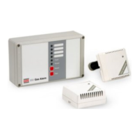
The GDS 202 GAS ALARM is a technical device designed for gas detection and alarm. It comprises a control unit and various sensors, offering comprehensive monitoring capabilities for different gas types.
The primary function of the GDS 202 GAS ALARM is to detect the presence of gas and trigger alarms to alert users of potential hazards. The system operates by continuously monitoring gas levels through its connected sensors. When gas is detected, it initiates a multi-stage alarm process: a pre-alarm state followed by a full alarm if the gas concentration persists. The control unit manages sensor inputs, processes alarm conditions, and activates visual and audible indicators, as well as relay outputs for external actions.
The system incorporates a stabilization period upon power-up, during which all alarm functions are held off for 3 minutes to allow sensors to stabilize. After this period, any sensor detecting gas will trigger a local visual (red LED) and audible alarm. Simultaneously, a signal is sent to the control unit, initiating an intermittent audible pre-alarm and a flashing red alarm LED, with the pre-alarm relay changing state. If the gas clears within 45 seconds, the system returns to normal operation. However, if the gas remains for longer than 45 seconds, a full alarm condition is activated, indicated by a constant red alarm LED and sounder, and the full alarm relay is activated. The audible alarm can be silenced at any time, but the full alarm indication remains latched until the gas has cleared, after which the system can be reset by pressing the reset pad.
The device also features fault monitoring, which detects issues with the sensor, sensor cable, or control unit, indicated by an amber LED and sounder. This fault indication is non-latching.
The control unit should be mounted in an accessible position within the field of vision, avoiding locations directly above cooking appliances or sinks. Mains supply should come from a 1A fused unswitched outlet to BS5733. Internal wires must be routed away from electronic components. Sensor positioning is critical and depends on the type and density of the gas:
After cable termination, specific link adjustments are required:
The system can be electrically tested by pressing the test pad on the control unit for 15 seconds, which initiates the pre-alarm state (without relay operation). Holding the test pad for an additional 15 seconds will trigger a full alarm condition, including the operation of both alarm relays. Each sensor has an individual test switch that, when pressed, simulates gas presence, turning the green LED to red and activating the sounder. For a comprehensive check, each sensor should be exposed to test gas, ideally every six months. During test periods, alarm relays can be inhibited by pressing the reset pad for 15 seconds. This illuminates the fault indicator and maintains all relays in the normal non-alarm state. Pressing the reset pad again for 15 seconds removes the inhibit.
Relays can be individually set to be normally energized or de-energized. This is done by pressing and holding the test button, then within 2 seconds pressing and holding the reset button. After 15 seconds, all alarm LEDs will turn on. Releasing both buttons immediately sets the relay.
Regular testing of the system is crucial to ensure its proper functioning. Exposing each sensor to test gas at least every six months is recommended. The ability to inhibit alarm relays during testing prevents unnecessary disruptions. The fault monitoring system provides immediate alerts for any issues with sensors, cabling, or the control unit, facilitating timely maintenance and repairs.
If the apparatus alarm sounds, immediate actions are required:
| Brand | GDS |
|---|---|
| Model | 202 |
| Category | Security System |
| Language | English |