8
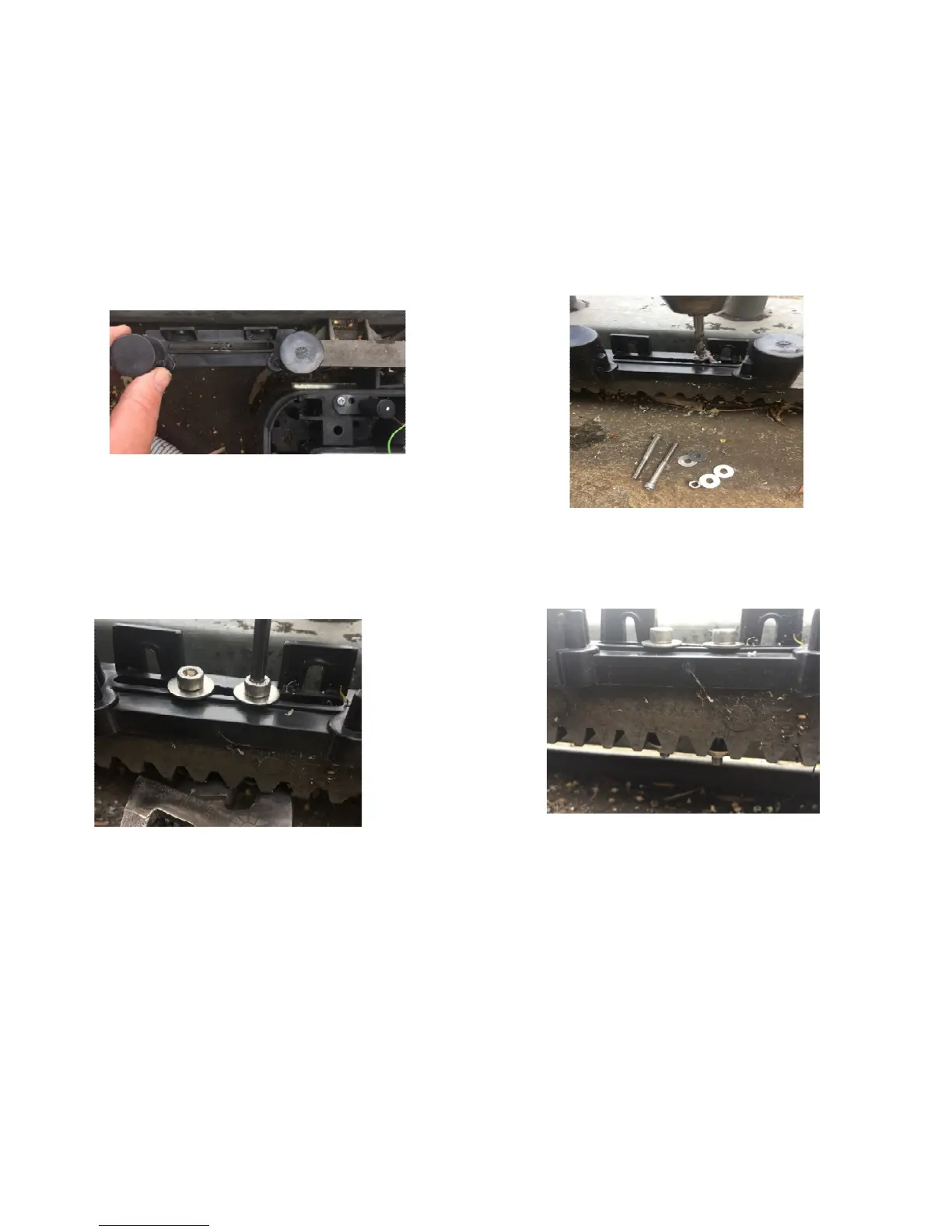
2. With the gate fully closed, hold the limit actuator on top of the rack so the leading edge of the
actuator is about 20 to 40mm away from the limit switch. Mark positions to drill 2 x 5mm holes as shown
below.
*Tip: With the operator powered up, you can see when the limit switch activates, by keeping an eye on the
cl and ol led indicators, so when the led turns on, you have reached the approx. close stop positon. So once
you see the led turn on, then move the limit actuator approx. 20mm forward from this position, this will then
give you a more accurate final position for the bracket to allow for run on of the gate.
Make sure you drill between the valleys of the rack, and mount using the supplied 5mm stainless bolts
shown above.
Do the same for the open limit actuator. Once the operator is running, you can slide the actuator across to
fine tune the final stopping position of the gate.
Electrical Connections
Supply
• ANE 240v 3A fused input terminals are provided pre wired with a 3 pin plug top.
• Supply transformer rated at 240vac primary, 15vac 15VA secondary.
Power for accessories
12vdc regulated supply terminals available on control board.
 Loading...