Do you have a question about the GE Medical Systems PRODIGY and is the answer not in the manual?
Instructions for using the service manual effectively.
Details required when requesting assistance from GE-LUNAR.
General safety precautions and guidelines for servicing the PRODIGY system.
Identification and explanation of safety symbols and labels on the PRODIGY.
Description and function of the emergency stop button on the PRODIGY.
Safety information regarding laser exposure during PRODIGY operation.
Explanation of the shutter indicator symbols and their meaning.
Explains the meaning of caution, warning, and note statements in the manual.
Discusses specific safety concerns like pinch points, laser, and radiation safety.
Guidelines for safely connecting computers and accessories to the PRODIGY system.
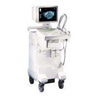
Overview of the PRODIGY system components and mechanical design.
Discussion of PRODIGY electronics, including cautions and internal components.
Block diagrams illustrating the PRODIGY system architecture and power distribution.
Lists fuses used in PRODIGY I and PRODIGY II systems.
Details on the Single Board Controller (SBC) for PRODIGY I systems.
Information on the Combined Single Board Controller (cSBC) for PRODIGY II systems.
Explanation of power distribution for PRODIGY II systems.
Details about the tube head and x-ray insert, including generation and spectrum.
Information on the x-ray generator and high voltage power supplies.
Function and power supply details for the MAX Board.
Description of the XORB Board's role in circuit protection.
Overview and operation of the detector subsystem.
Functions and motion control of the FOINK board.
Description of the PRODIGY display panel and its indicators.
Explanation of the audible signal for X-RAY OFF status.
Details on the X-ray collimator subsystem and its components.
Specifications for PRODIGY components, functional, and environmental details.
Procedures for secondary calibration and daily quality assurance.
Overview of the diagnostic software and how to access it.
Explains the functions available within the Tools menu of the service software.
Details on various diagnostic tests available in the software.
Describes different scan modes used for diagnostics.
Information on maintaining and reading the system's error log.
Procedure for printing the diagnostic error log.
How to use the integrated troubleshooting help software.
Lists diagnostic failure codes and their associated causes.
Troubleshooting steps for transverse motion failures and binding.
Troubleshooting steps for longitudinal motion failures and binding.
Steps to diagnose and resolve 28V power supply failures.
Troubleshooting issues related to the emergency stop button.
Diagnosis of problems related to the tube head thermostat.
Troubleshooting communication issues between system components.
General troubleshooting for other diagnostic failure codes.
Steps to diagnose failures in Quality Assurance tests.
Troubleshooting unstable or decreasing reference counts.
Identifying and resolving arcing issues in the system.
Troubleshooting common imaging artifacts and problems.
Diagnosing failures indicated by alignment test results.
Troubleshooting issues with system indicator lights.
Steps to diagnose communication loss between components.
How to interpret and analyze QA history data.
Troubleshooting procedures for the MAX Board.
Troubleshooting procedures for the FOINK Board.
Troubleshooting procedures for the OMI Board.
Troubleshooting procedures for the SBC Board.
Troubleshooting procedures for the XORB Board.
Troubleshooting procedures for the Detector Motherboard.
Troubleshooting procedures for the Detector Daughter Boards.
Procedure for reloading the LUNAR software on the system.
Procedure for peaking the detector to ensure optimal performance.
Steps for replacing the tube head assembly.
Procedure for replacing the lower cable bundle.
Procedure for replacing the upper cable bundle.
Procedure for replacing the tube head control cable.
Tests to be performed after specific service procedures.
Guidelines for returning parts to LUNAR for international distributors.
Overview of preventative maintenance procedures and checks.
Importance of checking QA History during preventative maintenance.
Procedure for repacking high voltage cable connectors during PM.
Checking scanner parts for signs of wear.
Procedures for cleaning the scanner components.
General inspection of the scanner for damage and connections.
Troubleshooting common unusual sounds during scanner operation.
Information on engineering changes noted in future revisions.
| Technology | Dual-energy X-ray absorptiometry (DXA) |
|---|---|
| Power Requirements | 100-240 VAC, 50/60 Hz |
| Application | Bone mineral density measurement |
| Scan Regions | forearm, whole body |
| Measurement Sites | Spine, hip, forearm |
| Applications | Osteoporosis diagnosis, body composition analysis |