FireShield Technical Reference Manual 1.1
Chapter 1
System overview and operation
System overview
FireShield is available in three models: three-zone, five-zone,
and ten-zone. Each model is similar except for the number of
initiating device circuits (IDCs) and notification appliance
circuits (NACs), as shown in the following table.
Model IDCs NACs
FS302 (three-zone) 3 2
FS502 (five-zone) 5 2
FS1004 (ten-zone) 10 4
Model numbers may have the following suffixes: G or R
indicates gray or red enclosure, GD or RD indicates panel with
FSDACT, GC indicates ULC panel with terminal shield, GF
indicates a French ULC panel with terminal shield, and G-2
indicates 230 Vac input.
Each panel is configured for Class B operation. All models
except for the three-zone can be easily converted to Class A
by using two Class B circuits to make one Class A circuit.
FireShield has the following optional components:
• Remote System Indicator (FSRSI)
• Remote Zone Indicator (FSRZI-A)
• Remote Relay Module (FSRRM)
• Power Expander Transformer (XTR3A120, XTR3A230)
(ten-zone only)
• DACT (Dialer)/Modem (FSDACT)
• City Tie Module (CTM4.7)
• Reverse Polarity Module (RPM)
• Battery Cabinet (BC-2)
Refer to Chapter 2 “Installation” for optional module details.
Operations overview
The panel operates in normal mode in the absence of any
alarm, supervisory, trouble, or monitor events. In normal
mode, the control panel monitors the system.
The panel operates in off-normal mode any time an event is
introduced into the system. When this happens, the panel:
• Changes contact positions on appropriate common relays
• Activates alarm outputs (for alarm events only)
• Turns on the appropriate LEDs and the panel buzzer
• Executes the appropriate programmed output response for
the input that signaled the event
• Communicates event information to appropriate optional
components (FSRSI, FSRZI-A, CTM4.7, or RPM)
If the optional FSDACT is installed, the panel:
• Sends a record of the event to the FSDACT LCD and to
the history log
• Uses the FSDACT to transmit event messages to a
monitoring station as programmed
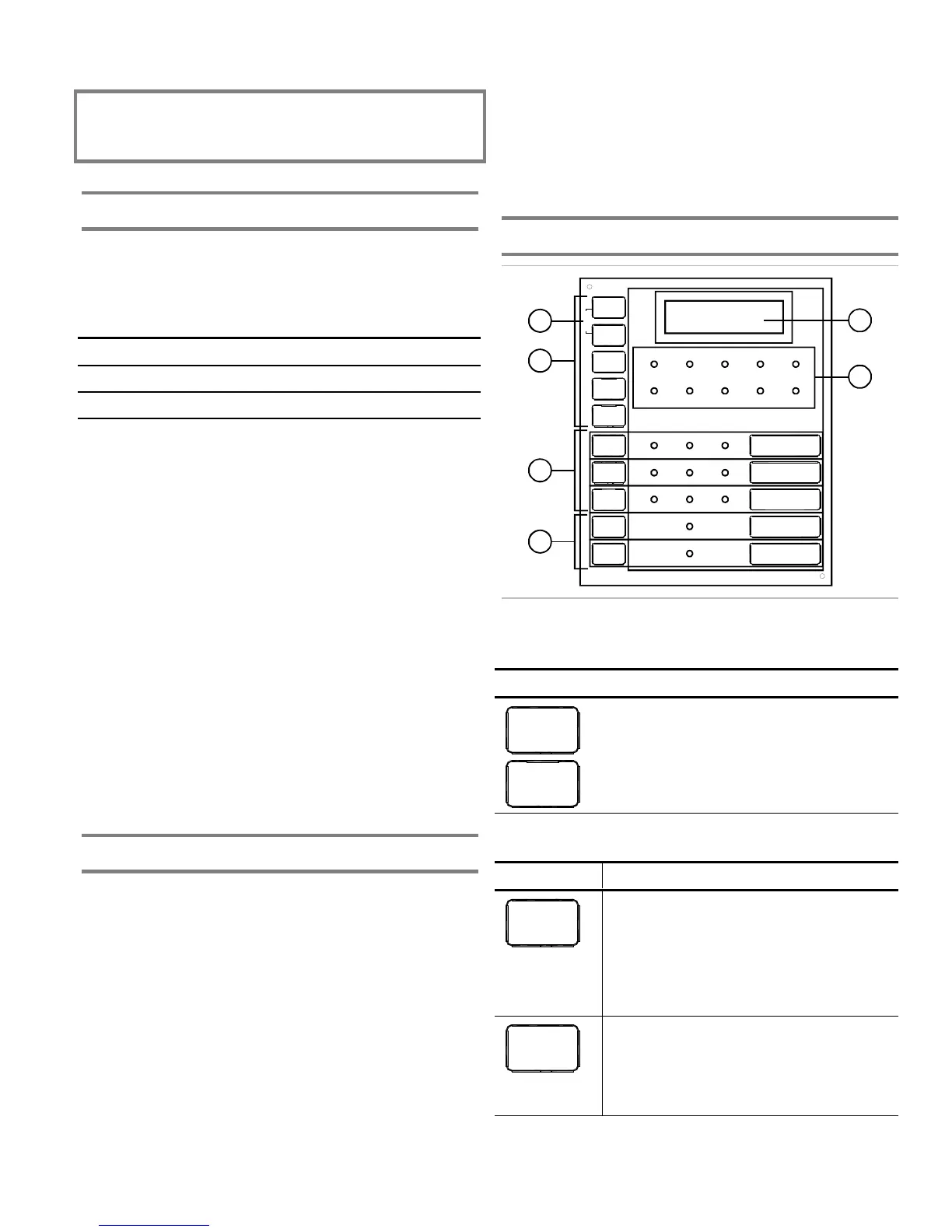
Controls and indicators
1
2
3
5
4
3
2
REMOTE
DISCON-
NECT
WALK
TEST
RESET
SIGNAL
SILENCE
& DRIL L
PA NEL
SILENCE
DISABLE
DISABLE
DISABLE
DISABLE
DISABLE
NAC 2
NAC 1
ALARM TROUBLE SUP/MON
ALARM
SUPTROUBLE POWER DISABLE
SIGNAL
SILENCED
WALK
TEST
GND
FAULT
BATT
TROUBLE
ANNUN
TROUBLE
LAMP TEST
1
6
Front panel display
(1) Lamp test
Buttons Description
REMOTE
DISCON-
NECT
WALK
TEST
Press the Remote Disconnect and Walk Test
buttons simultaneously to initiate a panel
lamp test. This lets you verify proper
operation of the LEDs on the panel and the
remote annunciators.
(2) Control buttons
Button Description
REMOTE
DISCON-
NECT
Operating mode with FSDACT: Disables or
enables FSDACT. Has no effect on alarm
relay.
Operating mode without FSDACT: Disables
or enables the common alarm relay.
Programming mode: Selects the next option.
WALK
TEST
Operating mode: Places the panel in walk
test mode. The Walk Test LED is on when
the panel is in walk test mode.
Programming mode: Selects the previous
option.