Calculations
A.2 FireShield Technical Reference Manual
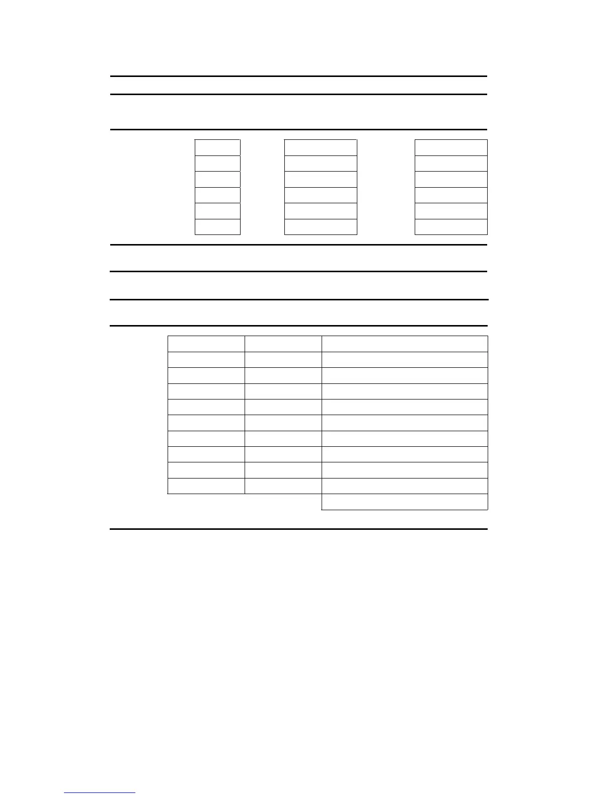
Form A
Module Quantity
Standby
current
(mA)
Qty × Standby
current (mA)
Alarm
current
(mA)
Qty × Alarm
current (mA)
FSRSI [1] 12 48
FSRZI-A [1] 8 35
FSRRM common [1] 30 41
FSRRM zone [1] 8 65
Other AUX
Total AUX [5] [6]
Form B
(Note: Calculate IDC detector load or use maximum load.)
IDC
Quantity of
detectors [2]
Detector current
(mA) [3]
Total standby current [4]
(quantity x current in mA)
IDC1
IDC2
IDC3
IDC4
IDC5
IDC6
IDC7
IDC8
IDC9
IDC10
Total current for all IDCs =
Max IDC standby current: FS302 = 4.5 mA, FS502 = 7.5 mA, and FS1004 = 15.0 mA
Notes
[1] Use of FSRSI, FSRZI-A, and FSRRM is limited as follows: Three- and five-zone panels support 2 FSRSIs, 2 FSRZI-As, and 4
FSRRMs, ten-zone panels support 2 FSRSIs, 4 FSRZI-As, and 6 FSRRMs.
[2] See the FireShield UL and ULC Compatibility List (P/N 3100468) for the maximum number of detectors per IDC.
[3] See FireShield UL and ULC Compatibility List (P/N 3100468) for detector current ratings.
[4] Maximum current per IDC may not exceed 1.5 mA.
[5] Aux power supplied by panel cannot exceed 0.5 A. If more than 0.5 A is required, you must use a compatible UL/ULC listed
fire alarm power supply.
[6] When using an auxiliary power supply, you must connect the -24 OUT connection on the panel to the negative connection on
the auxiliary power supply. Refer to the installation section for more information.