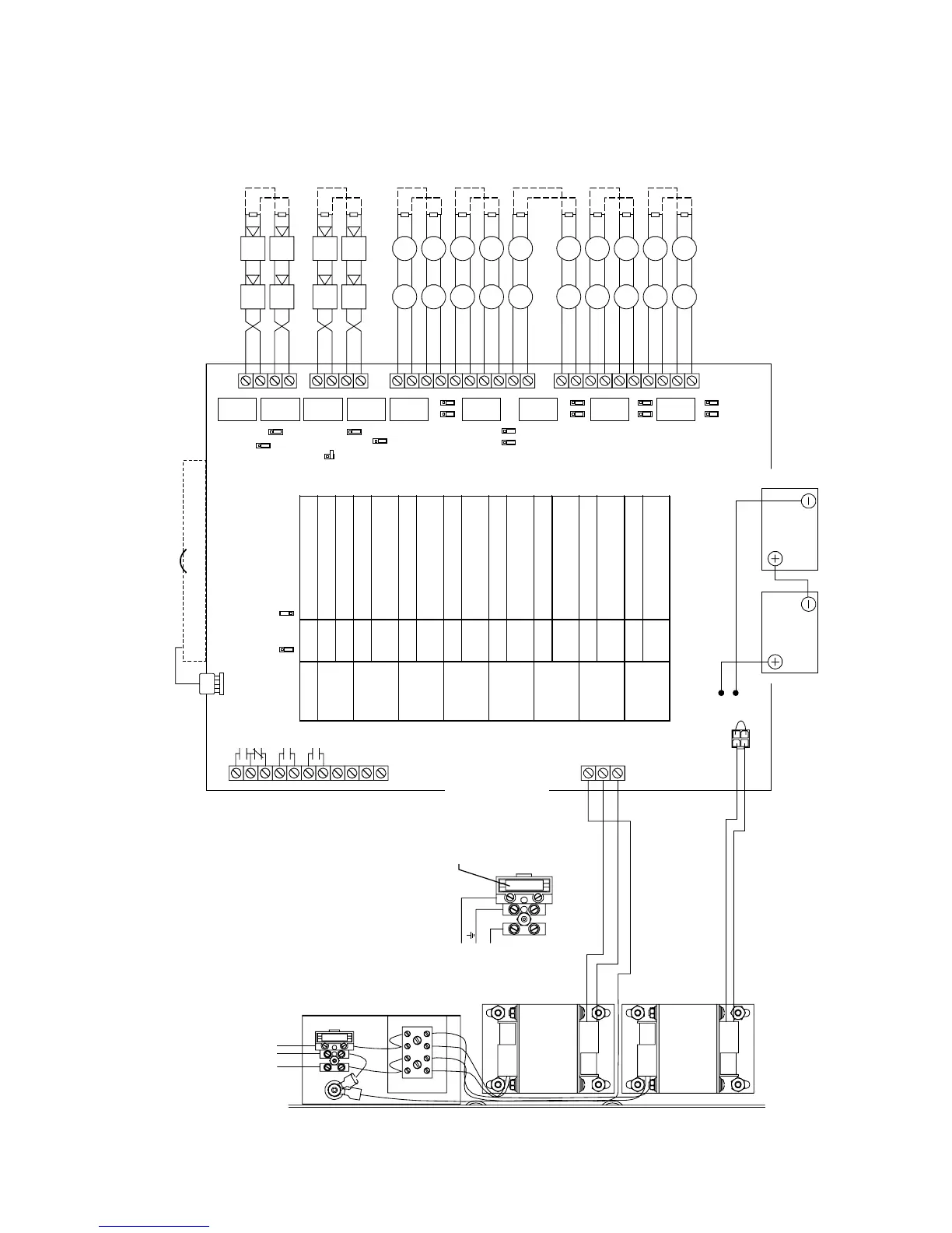
Jumper settings and wiring diagrams
FireShield Technical Reference Manual C.5
Ten-zone panel
E1
E2
RED
BLACK
C–
C+
24VOUT–
24VOUT+
Jumper Position Description
PRG OFF Normal mode
ON Programming mode
JP1 & JP13 B NAC1 and NAC2 = Class B
A NAC1 = Class A out
NAC2 = Class A return
JP6 & JP14 B NAC3 and NAC4 = Class B
A NAC3 = Class A out
NAC4 = Class A return
JP2 & JP3 B IDC1 and IDC2 = Class B
A IDC1 = Class A out
IDC2 = Class A return
JP4 & JP5 B IDC3 and IDC4 = Class B
A IDC3 = Class A out
IDC4 = Class A return
JP7 & JP8 B IDC5 and IDC6 = Class B
A IDC5 = Class A out
IDC6 = Class A return
JP9 & JP10 B IDC7 and IDC8 = Class B
A IDC7 = Class A out
IDC8 = Class A return
JP11 & JP12 B IDC9 and IDC10 = Class B
A IDC9 = Class A out
IDC10 = Class A return
EGND
24VAC
IN
12 Vdc
Battery
MAIN SUPPLY CIRCUIT
120 V, 60 Hz, 1.6 A
230 V, 50/60 Hz, 0.8 A
from dedicated branch supply
+
–
+
–
NAC1–
NAC2+
NAC2–
NAC1+
NAC3–
NAC4+
NAC4–
NAC3+
+
–
+
–
IDC6–
IDC6+
IDC7–
IDC7+
IDC8–
IDC8+
IDC9–
IDC9+
IDC10–
IDC10+
EOLR
+
–
+
–
+
–
+
–
EOLR
INITIATING DEVICE CIRCUITS
[2] [3] [9] [12]
Class B (Style B) or Class A (Style D)
Operating voltage: 16.3 - 25.7 Vdc
Operating current: 1.5 mA/circuit, max
Circuit impedance: 13 , 0.03 F
Ωµ
EOLR: 4.7 k , 1/2 W (P/N EOL4.7)
Ω
CAUTION:
The middle connection on the
terminal block makes a mechanical connection
to the chassis even with the ground wire removed.
CAUTION:
The panel does not indicate when
JP13 or JP14 are missing. A shorted NAC circuit
may damage the equipment if NAC jumpers are
missing or set incorrectly.
CAUTION:
Break the wire run at each field device to
provide proper connection supervision.
Do not loop wires under terminals.
NOTIFICATION APPLIANCE CIRCUITS
[2] [3] [5] [8] [12]
Class B (Style Y) or Class A (Style Z)
Operating voltage: 24 Vfwr
Operating current: 1.5 A/circuit, 2.5 A total
Circuit impedance: 13
Ω
, 0.03
µ
F, m a x
EOLR: 4.7 k
Ω
, 1/2 W (P/N EOL4.7)
SEE DETAIL A
DETAIL A
L
N
LINE
EARTH GND
NEUTRAL
12 Vdc
Battery
XTR3A120
or
XTR3A230
(OPTIONAL)
TB2
TB4
TB5
TB6
TB3
TB1
IDC1–
IDC1+
IDC2–
IDC2+
IDC3–
IDC3+
IDC4–
IDC4+
IDC5–
IDC5+
JP14
JP1
JP13
PRG
JP6
JP3 & JP2
JP4 & JP5
JP7 & JP8
JP9 & JP10
JP11 & JP12
= B = A
COMMON TROUBLE RELAY
[11]
1 A @ 30 Vdc, resistive
Nonsupervised
COMMON SUPERVISORY RELAY
[11]
1 A @ 30 Vdc, resistive
Nonsupervised
COMMON ALARM RELAY
[11]
1 A @ 30 Vdc, resistive
Nonsupervised
REMOTE MODULE
COMMUNICATION BUS
13 , 0.03 F, max
Ωµ
AUXILIARY/SMOKE
POWER OUTPUT
24 Vdc,nominal @ 500 mA
5A, 250V, SLO-BLO
(Littlefuse P/N 218005)
+
–
+
–
+
–
+
–
+
–
+
–
+
–
+
–
+
–
+
–
+
–
+
–
+
–
+
–
+
–
+
–
+
–
+
–
+
–
+
–
RECHARGEABLE BATTERY CIRCUIT
Voltage: 24 Vdc
Amp-hour capacity: 18 Ah maximum sealed
lead acid batteries only
DACT/Dialer (optional)
J2
JP1 wire loop [13]
DACT
connector
WARNING:
Never replace
fuse while circuit is energized.
Replacement fuse must be of
equivalent size and type.