GE Infrastructure Security Pty Ltd 5
Before you begin
Before you can successfully install the reader you need to know some details about the system, depending on
whether the reader is to be normally used in on-line or off-line mode. These modes are described in the following
sections.
On-line mode
A reader connected to an Alliance, Challenger, or a 4-door/4-lift intelligent access controller LAN, is said to be on-
line, and you need to know:
• The LAN address.
• The system layout, in order to fit the LAN termination end-of-line resistor (if required).
• Whether you need to install RTE (request to exit, or egress), via a push button or a TS0064 Expanded Button
Interface.
• Whether the reader is to be powered from the LAN or from a separate 12 V power supply. Do not power the
reader from the LAN if the cable length to the control panel (or 4-door/4-lift intelligent access controller) is
greater than 100 metres.
If the new reader is to be used on an Alliance or Challenger LAN, or a 4-door/4-lift intelligent access controller LAN,
you must have some means to program polling to the new reader, such as:
• By using a RAS with a liquid crystal display (LCD) on the LAN.
• By using the system’s management software (e.g. TITAN, ARES, or Alliance).
Off-line mode
A reader connected to a Wiegand or magnetic stripe interface, is said to be off-line, and you need to know:
• Whether a tamper input is required. If a tamper input is required you need to connect a 10K resistor via the
violet wire (see
Figure 4) to a zone input, and configure the open collector output as Tamper. See RAS Menu
Option 8. Open Collector Output
on page 12. For later versions of 4-door/4-lift intelligent access controller
firmware, the reader watch dog option may be used to monitor the reader tamper. See
Using tamper
functionality
on page 6.
• Whether the reader is to be programmed for one-wire or two-wire LED control. See RAS Menu Option 2. LEDs
Off-Line
on page 12.
Mounting the reader
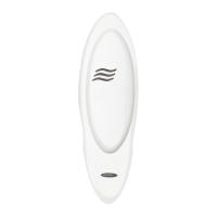
Mount the reader on any flat surface with two pan-head screws, 3.0 mm to 3.5 mm diameter. Do not use
countersunk screws, as they may damage the reader.
When mounting TS0870 or TS0870D readers:
• To remove the dress cover and expose the mounting screw holes, gently prise or pull cover from the main body.
Avoid using excessive force as you may damage the reader.
• If mounting in an outdoor environment, ensure that the blue LED is at the top.
• After mounting, gently press the cover over the main body until it locks into place.
A slightly reduced card reading range occurs when mounted on a metal surface.
LAN termination
Smart Card Readers are not fitted with a LAN termination ‘TERM’ switch or link. A 470 Ω end-of-line resistor
(supplied) is used for LAN termination. There must be only two LAN terminations used on any one LAN segment.
Connect the end-of-line resistor between the green and white wires (D+ and D-) when the reader is the last device
on the Challenger or Alliance LAN. In a star wiring configuration, the end-of-line resistor is required for readers that
are the last devices on the two longest LAN cable runs.
Programming the reader’s address
Smart Card Readers have a default LAN address of 16. Changing the LAN address is a programming item described
in
Programming on page 9.

 Loading...