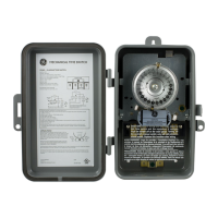
APPLICATION
The GE Time Switches (56135, 15087, 15207) are universal, electromechanical
time switches which can be field configured for various power supply
voltages. The voltage options include 120VAC, 208/240VAC and 277VAC – all
within the same unit! Selection of the desired supply voltage is easily achieved
by positioning dipswitches on the printed circuit board assembly (consult
Dipswitches Configuration on back). The mechanism is mounted in a NEMA
indoor or outdoor enclosure and is intended for the control of lighting, heating,
air conditioning, pumps, motors, or general electrical circuits in residential,
commercial, industrial and agricultural facilities.
SPECIFICATIONS
Input Voltage: 120 VAC, 208/240 VAC, or 277 VAC in all units based
upon dipswitch configuration.
15087 NEMA 3R Indoor & Outdoor BM-A301US5-O2
15207 NEMA 1 Indoor BM-A301US5-I2
56922 NEMA 1 Indoor BM-A301US5-I2
15132 NEMA 3R Indoor & Outdoor EM-A301US9-O2
Switch Rating: DPDT Models
Normally Open Contacts
40A Resistive, 120-277Vac.
30A General Purpose, 120-277Vac.
20A Resistive, 30Vdc
1 HP, 120Vac ; 2HP, 240Vac ;
20A Ballast, 120-277Vac.
15A Tungsten, 120Vac
5.4A Tungsten, 208-277Vac.
800VA, Pilot Duty, 120Vac.
720VA, Pilot Duty, 240-277Vac.
TV-5, 120Vac
Normally Closed Contacts
30A Resistive, 120-277Vac
15A General Purpose, 120-277Vac
15A Resistive, 30Vdc
20A Ballast, 120-277Vac
1/4HP, 120Vac; 1/2HP, 208-240Vac.
290VA, Pilot, 120Vac.
360VA, Pilot, 208-240Vac.
NOTE: If loads are connected to both NC and NO contacts, both contacts are
decorated to 67% of the above values.
ENVIRONMENTAL RATINGS
Ambient Temperature: –40F to 130F
Humidity: 0-95% RH, Non-condensing
WIRING CONNECTIONS
Screw clamp terminals for up to 2 AWG #8 wires per position. For supply
connections, use 8AWG or larger wires suitable for at least 105° C. Use copper
conductors only.
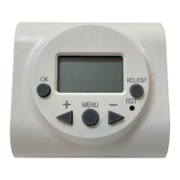
Lights
Power LED (Orange)
– Light illuminates when power is applied to
the timer
Status LED (Green)
– Light illuminates when power is applied to load.
Included Hardware
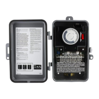
INSTALLATION
CAUTION: Before wiring or servicing, power to this time switch and the
equipment it controls must be turned off. Turning off the time switch only
will not prevent a shock hazard. Replace cover plate within housing before
supplying power to time switch. If you are not comfortable installing this
device please contact a licensed electrician. Before installing this product read
all instructions carefully.
Removing Knockout
1. Select knockouts to be used. Remove the inner 1/2” knockout by inserting
a flathead screwdriver on the inner most ring and carefully punching the
knockout loose. Remove slug. If the 3/4” knockout is required, remove the
outer ring with pliers after removing the 1/2” knockout. Smooth edges with
a knife if necessary.
Please refer to Quick Start Guide for Examples and More Details.
Mounting of the Time Switch Box
NOTE - Before mounting be sure to remove knockouts for the wires, (see Quick
Start Guide)
1. In order to mount the box you will need the 3 supplied anchors and 3
supplied screws from the hardware list above. (Anchors included are
designed for mounting on sheetrock.)
2. Using the box as a template, mark with a pencil where the three pilot holes
will be drilled.
Time Switch
WARNING
Risk of electric shock
•
Shut off power at fuse box or circuit
breaker box before installation
Risk of fire
•
Do not use to control receptacle
outlets
•
Do not exceed electrical ratings
•
Use copper wire only with this device
QTY Hardware
3 M4 Anchors 1” Long
3 M4 Screws 1” Long
2 8 AWG Jumpers for 240V AC
2 10 AWG Jumpers for 120V AC
1 Wire Nut (For Ground Wires)
15135 NEMA 3R Indoor & Outdoor
GE 15135 Indoor & Outdoor Timer
http://waterheatertimer.org/How-to-wire-GE-15135-timer.html
http://waterheatertimer.org/GE-timers-and-manuals.html#15135