Do you have a question about the GE 15163 and is the answer not in the manual?
Lists essential tools required for installation and setup.
Details the hardware provided with the timer for installation.
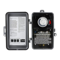
Critical safety instructions and precautions for installation and operation.
Instructions on how to remove 1/2" and 3/4" knockouts from the metal box.
Detailed steps for mounting the timer to drywall or plywood surfaces.
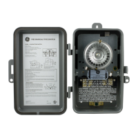
Explains the wiring diagram and lists terminal connections for 120VAC load.
Crucial safety warnings related to high voltage and electrical shock.
Instructions for safely removing the protective plastic guard.
Details on connecting the 120VAC hot, neutral, and ground wires.
Instructions for connecting the load's hot, neutral, and ground wires.
Guidance on correctly reinstalling the plastic guard after wiring.
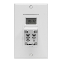
How to set the current time and desired ON/OFF states using the timer dial.
Procedure for checking connections and timer operation after 24 hours.
Specific information about the plastic guard on the back of the motor.
This document provides a quick start guide for installing and activating a timer, likely an electrical timer for controlling a load. It covers the necessary tools, hardware, installation steps, and important safety warnings.
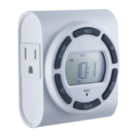
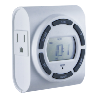
The device is an electrical timer designed to control a 120 VAC load. It allows users to program ON/OFF times for connected equipment. The timer includes a clock motor that drives the timing mechanism, and it is designed for both indoor and outdoor use. The core function is to automate the switching of an electrical circuit based on a set schedule, providing convenience and energy management.
Installation and Mounting: The timer comes in a metal box with pre-punched knockouts (1/2" and 3/4") for wire entry. Instructions detail how to remove these knockouts using a screwdriver and pliers. For mounting, the timer box has three designated holes. Users can choose to mount it on drywall or plywood. For drywall, 3/16" holes are drilled for drywall anchors, which are then gently tapped into place with a hammer until flush with the wall. The timer is then secured to these anchors using supplied screws. For plywood, 3/32" holes are drilled for screws, and the timer is mounted directly.
Wiring (120 VAC Single Load Setup): The wiring process involves several steps to ensure proper and safe connection.
Timer Activation:
Special Note on Plastic Guard (Motor Back): There is an additional plastic guard on the back of the motor for "Input" side connections. This guard snaps in and out easily. If it becomes dislodged during shipment or installation, it should be reinstalled by placing its two tabs into the appropriate slots.
Safety Warnings and Best Practices: The document emphasizes several critical safety and maintenance points:
Post-Installation Check (After 24 Hours): After 24 hours of operation, users are advised to perform a check:
Operating Instructions: Users are encouraged to review the "Operating Instructions" in the user manual for more detailed guidance on using the timer.
| Voltage | 120V |
|---|---|
| Max Load | 15A |
| Programmable | Yes |
| Display | LCD |
| Battery Backup | No |
| Number of Outlets | 1 |
| Amperage | 15A |
| Wattage | 1800W |
| Color | White |
| Indoor/Outdoor | Indoor |
| Number of Programs | 7 |
| Mounting Type | Plug-in |
| Type | Digital |
| Load Rating | 15A |