3
External contact wiring
Use the following specifications for the external contact:
• Maximum wire length: 26 ft. (8 m).
• Wire: Stranded, 22-gauge (0.7112 mm).
• Switches: Hermetically sealed external switches (sealed
reed switches) that supply a minimum 250 ms open or close
on alarm.
Note: Do not connect more than five external contacts to a door/
window sensor.
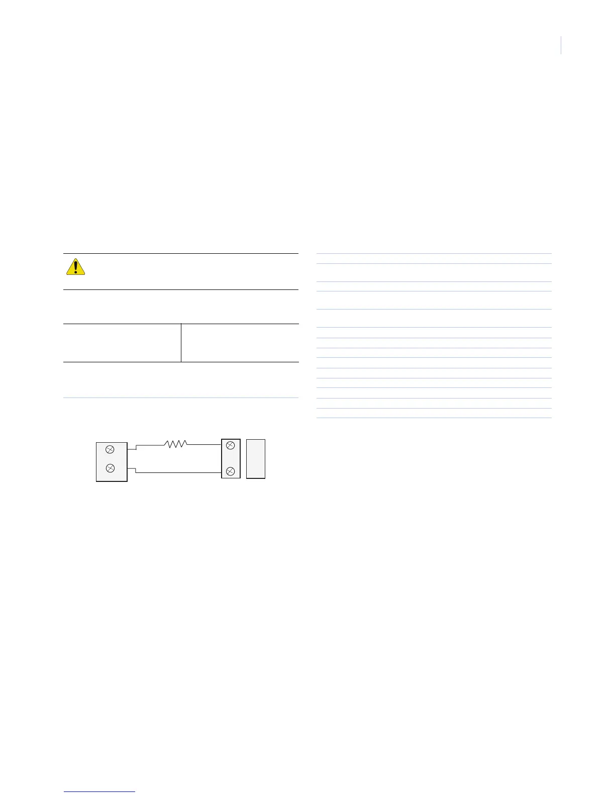
You can wire the sensor terminal blocks with leads from an
external contact (Figure 8). The door/window sensor provides
alarm and tamper indication. Wire the external contact with one
end-of-line (EOL) resistor in series with the external contact.
This gives the following readings for each configuration:
Figure 8 shows external contact wiring (normally closed and
normally open).
Figure 8. External contact wiring
Sensor test
The sensor test verifies proper communication between the
sensor and the panel/receiver. To test the sensor, refer to the
specific panel/receiver documentation and do the following:
1. Put the panel/receiver into sensor test mode.
2. Open the door/window the sensor is protecting. The sensor
transmits a signal.
3. Listen for siren beeps to determine the appropriate response.
4. Exit sensor test mode.
Battery replacement
When the system indicates low sensor battery, replace it immedi-
ately. Use the recommended replacement batteries (see
Specifica-
tions
).
To replace the batteries:
1. Remove the sensor cover.
2. Remove the battery. Follow local laws for battery disposal.
3. Insert the replacement battery, observing correct polarity
(Figure 3 on page 1).
4. Perform a sensor test with the panel. See Sensor test.
Specifications
CAUTION: You must install the EOL resistor at the
external detection device for proper supervision.
Normally closed
Zero ohm/short = Tamper
4.7 kohm = Normal
Open = Alarm
Normally open
Zero ohm/short = Tamper
4.7 kohm = Alarm
Open = Normal
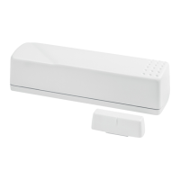
Door/Window
Contacts
EOL resistor
Sensor
4.7 Kohm
Model number Brown: 60-362N-11-319.5
White: 60-362N-10-319.5
Frequency 319.5 MHz
Compatibility GE Security 319.5 MHz control panels/
receivers
Battery type 3.0 V, 1300 mAh lithium
Required batteries Duracell DL 123A, Panasonic CR123A, Sanyo
CR123A, Varta CR123A
Estimated battery life 5 to 10 years at 20°C (68°F) depending on the
number of activations per day
Magnet gap 3/8 in. (max.)
Supervisory interval 64 minutes
End-of-line resistor 4.7 Kohm
Typical RF output power 0.25mW EIRP
Operating temperature 10 to 120°F (-12 to 49°C)
Storage temperature -30 to 140°F (-34 to 60°C)
Relative humidity 0 to 90% noncondensing
Dimensions (L x W x D) 3.02 x 1.5 x 1.02in. (81 x 38 x 26 mm)
Weight 44 g
Listings UL 1023, UL 1610
FCC This device complies with part 15 of the FCC rules. Operation is
subject to the following conditions:
This device may not cause harmful interference.
This device must accept any interference received, including inter-
ference that may cause undesired operation.
Changes or modifications not expressly approved by the party
responsible for compliance could void the user’s authority to
operate the equipment.
FCC ID: B4Z-914D-DWS
Technical support
Toll-free: 888.GESECURity (888.437.3287 in the US, including Alaska and Hawaii; Puerto Rico; Canada).
Outside the toll-free area: Contact your local dealer.
www.gesecurity.com
 Loading...