3
ESL 429/449
Supervision of System Wiring
Power wiring in four-wire systems is required by NFPA 72 to be
supervised. This is accomplished by installing a power supervi-
sion relay at the end of the detector power circuit. The contacts of
the supervision relay are wired in series with the system’s alarm
initiating circuit, and are closed when energized (see Figure 5). A
break in the detector power circuit or a loss of power de-energizes
the power supervision relay, opening the contacts and causing a
trouble annunciation at the fire alarm control unit.
ESL models 204-6 V and 204-12/24 V are relays UL Listed for
four-wire power supervision. Models 449CTE and 449CSTE are
smoke detectors with a built-in end-of-line power supervison
relay, and can be used to supervise a circuit in place of a power
supervison relay. The 449CTE and 449CSTE will also automati-
cally send a trouble signal to the control panel whenever the
detector needs maintenance.
Installation Test
After all connections are complete and the wiring is checked for
errors, apply power to the system. There should be no alarm. If
an alarm is reported, determine if a detector is latched in alarm or
if there is a problem with the wiring.
Smoke Test
The units should be tested in place annually using one of the
following methods:
A. Use Smoke! in a can
®
and follow the directions on the can.
B. Hold a smoldering punk or cotton wick close to the unit
and gently direct the smoke into the smoke entry openings
for 20 seconds or until an alarm is indicated.
Be sure to properly extinguish the smoke source after
testing! This is a go/no go test and is not a reliable indication of
detector sensitivity. If it is successful, the LED will remain lit.
To reset the detector, operate the system reset switch to remove
power from the detectors. The control unit alarm and all
auxiliary functions should be verified for a complete test of each
detector.
Heat Test
Models with heat sensors sample for heat every 3 seconds. Test
heat sensors by using a hot air gun. Aim the gun at the heat
sensor from 6-10 inches (15-25cm) away. The detector should go
into alarm in less than 30 seconds.
+
–
++--
+
+
--
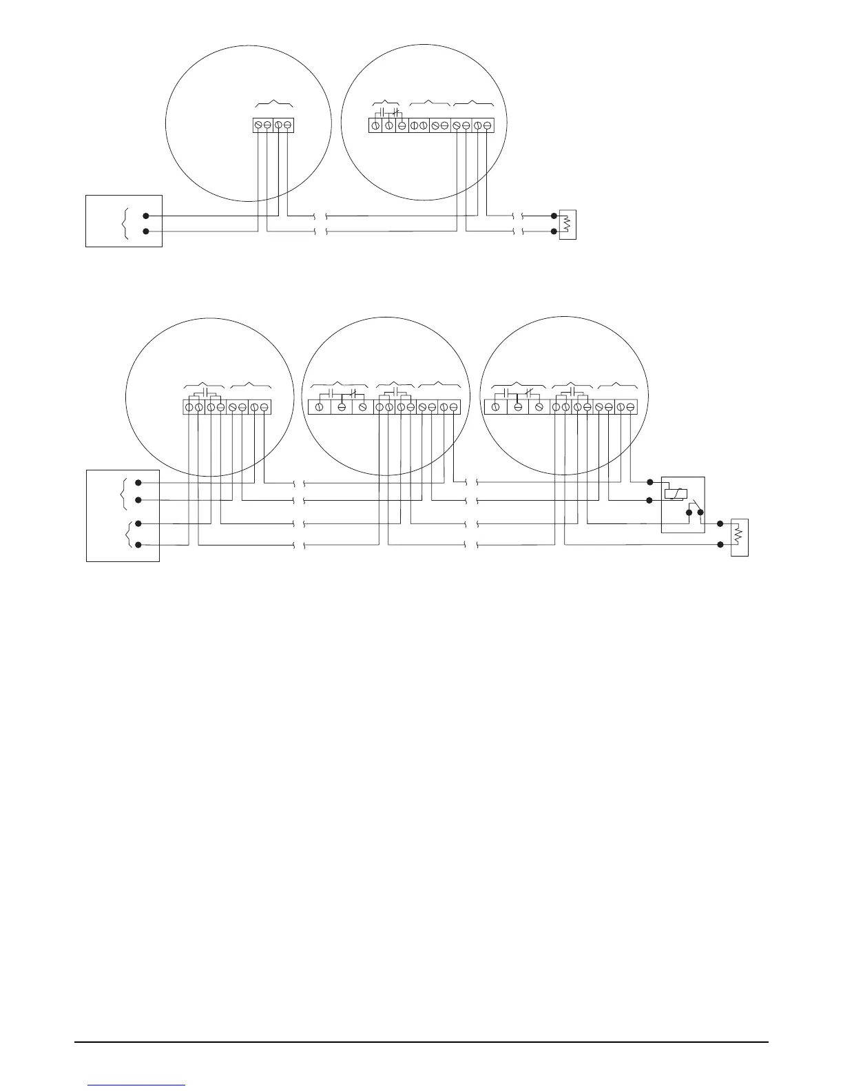
429 Series Wiring Diagram
first detector
last detector
Compatible Listed
Control Unit*
fire alarm
initiating
circuit
Models 429AT, 429C,
429CT, 429CST
Model 429CRT
power
powernot used
auxiliary
contacts
End-of-Line
Device
* Two-Wire Compatibility
Refer to ESL’s Compatibility
Index for compatible control
panel listings.
449 Series Wiring Diagram
Figure 5. Wiring Diagrams
+
–
++--
+
+
--
++
--
first detector
last detector
fire alarm
initiating
circuit
DC
power
circuit
Listed Control Unit
Power
Supervision
Unit
power
Models 449
CSRH*
Models 449
CRT, CSRT
Models 449
AT, C, CT, CST
local non-
latching
smoke alarm
contacts
heat sensor
contacts
power
alarm
contacts
auxiliary
contacts
power
alarm
contact
red
black
brown
brown
* The 449CSRH units
are smoke alarms with
isolated heat detectors.
End-of-Line
Device