Do you have a question about the GE FHSD720C and is the answer not in the manual?
Defines typographic conventions used in the document.
Defines icons used in the document for warnings and notes.
Provides contact information for GE Security representatives.
Details laser classification and FDA regulations for the product.
Covers UL and EN54-20 requirements for detectors.
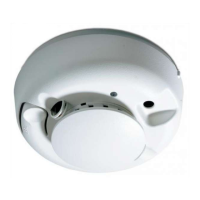
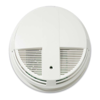
Details the different FHSD700C detector models and their features.
Explains how the system monitors air flow for blockages and disconnections.
Describes the different alarm states and trace mode functionality.
Details the detector's display panel, buttons, and LEDs.
Details the functions of the detector's control and configuration buttons.
Describes the function of the status display.
Explains the alternate functions of buttons indicated by LEDs.
Details the indicators for sector status, alarms, and faults.
Provides descriptions for all LEDs on the detector display.
Explains the operation of Alert, Action, Fire1, and Fire2 indicators.
Describes the logarithmic smoke density bargraph display.
Provides guidelines and considerations for mounting detector units.
Details the power, input/output, and communication cable connections.
Covers accessing detector internals, power supply, and grounding.
Details specific interface connections for the FHSD720C model.
Defines input and output connections for various interfaces.
Provides guidelines for connecting sampling tubes to the detector.
Instructions for installing and configuring a remote display panel.
Describes the sequence of events during detector power up.
Procedure for normalizing air flow for detector calibration.
Specific steps for normalizing flow in wide bore systems.
Specific steps for normalizing flow in small bore systems.
Explains access levels and default codes for configuration.
Describes user functions associated with display panel buttons.
Details how to navigate through the detector's main menu modes.
Accessing fault lists and entering operator mode.
Accessing engineering parameters and configuring detector settings.
Details configuration parameters from OPCODE to FLOWLOG.
Details configuration parameters from SETFAN to SC_DEL.
Details NIGHSTART and TRC PRESS configuration parameters.
Setting alarm levels and delays for day/night operations.
Procedure for setting the detector's internal time and date.
Configuring network settings like IP address and subnet mask.
Overview of parameters available in the setup menu.
Laser calibration, defaults, maintenance, and testing modes.
Details on installing and configuring I/O modules like the relay module.
Steps for daily or weekly checks of the detector system.
Provides a schedule for detector servicing and relevant notes.
Visual guide for navigating the detector's display panel menus.
Guidelines for installing RS485 equipment and electrical supply.
Safety warnings and information regarding the laser chamber.
| Sensor Type | Photoelectric |
|---|---|
| Alarm Volume | 85 dB |
| Test Button | Yes |
| Low Battery Indicator | Yes |
| Hush Feature | Yes |
| LED Indicator | Yes |
| Power Source | Battery |
| Mounting Type | Wall or Ceiling |
| Type | Smoke Alarm |