FHSD700C Series Product Guide
GE Security
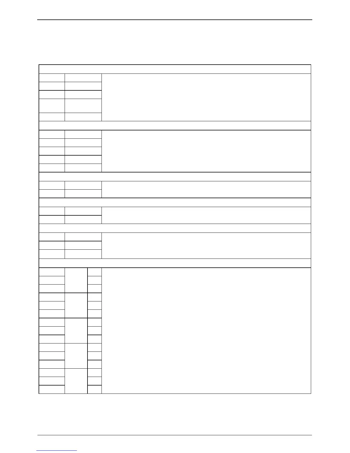
3.2.3 Connection Interfaces
The following tables define input and output connections for the FHSD700C Series.
Table 3-2: Connections for i602 I/O Board
CN1: RS232 Interface
2 Receive Data
3 Transmit Data
5 0 V
1, 4, 6, 7,
8, 9
N/C
Shell Earth (Screen)
Requires suitable twisted screened cable up to a maximum distance of 15 m.
CN2: DC Supply
1 24 VDC in
2 0 VDC in
3 N/C
4 N/C
5 Mains/Battery
Requires 16 x 0.25-15 A (18 AWG) cable (0.75mm
2
minimum IEC60227 H05 W-F/H05 WH2-F2
for EC).
Note: Link Pin 2 (0 V) and Pin 5 (MAINS/BAT). See External Power Supply Connection on page
9 for further details.
CN3: Auxiliary Supply Output Interface
1 0 VDC
2 24 VDC
Requires 7 x 0.2 - 6 A (24 AWG) cable (1 A maximum load).
CN4: Remote Reset Interface
1 - input
2 + input
Opto isolated input. 24 VDC low current signal.
CN6: RS485 Interface
1 Shield
2 RS485 -
3 RS485+
Belden 9842 cable (or suitable equivalent)
Note: Ensure that the Mid/End Jumper Link is fitted correctly on pins 7/8/9 of CN 5. Please see
Appendix B.1 on page 36 for further details.
CN7: Output Relay Interface
1 C
2 NC
3
FIRE 2
NO
4 C
5 NC
6
FIRE 1
NO
7 C
8 NC
9
ACTION
NO
10 C
11 NC
12
ALERT
NO
13 C
14 NC
15
FAULT
NO
Requires 7 x 0.2 - 6 A (24 AWG) cable
Note: Maximum relay contact rating is 2 A @ 30 VDC.
Note: Please see 4-Channel Relay Module on page 31 for further details.
Note: Connection CN14 is only used for special applications.
12
www.gesecurity.net