CHAPTER 4: SETPOINTS PROTECTION
845 TRANSFORMER PROTECTION SYSTEM – INSTRUCTION MANUAL 4–145
The fault current of 15000 Amps would then be translated as 15000/3000 = 5 times
winding 2 CT. Bringing this to the same scale with respect to winding 1 CT reference , i.e.
multiplying by a magnitude of 0.4521, the Break 2 setting would be:
Break 2 = 5 *0.4521 = 2.21 xCT (w1)
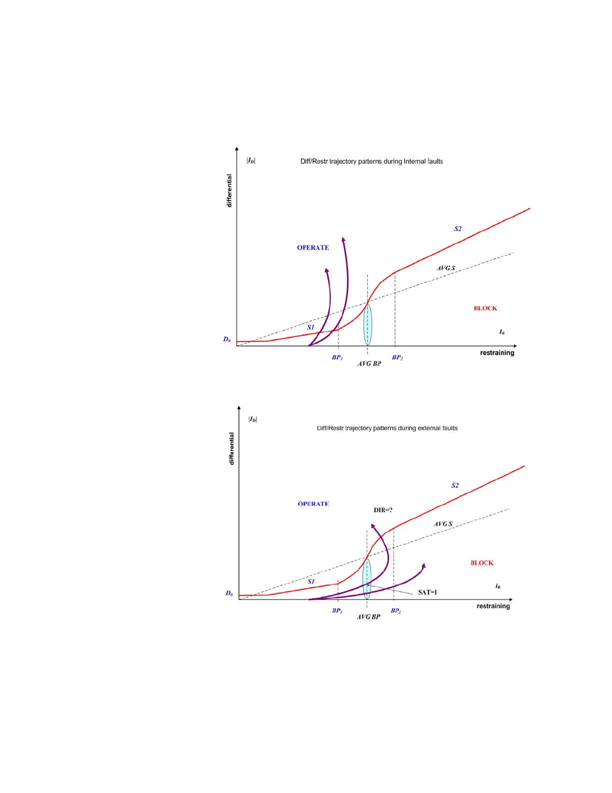
Figure 4-48: Examples of differential/restraint trajectory during internal fault
Figure 4-49: Examples of differential/restraint trajectory during external fault