CHAPTER 4: SETPOINTS PROTECTION
845 TRANSFORMER PROTECTION SYSTEM – INSTRUCTION MANUAL 4–199
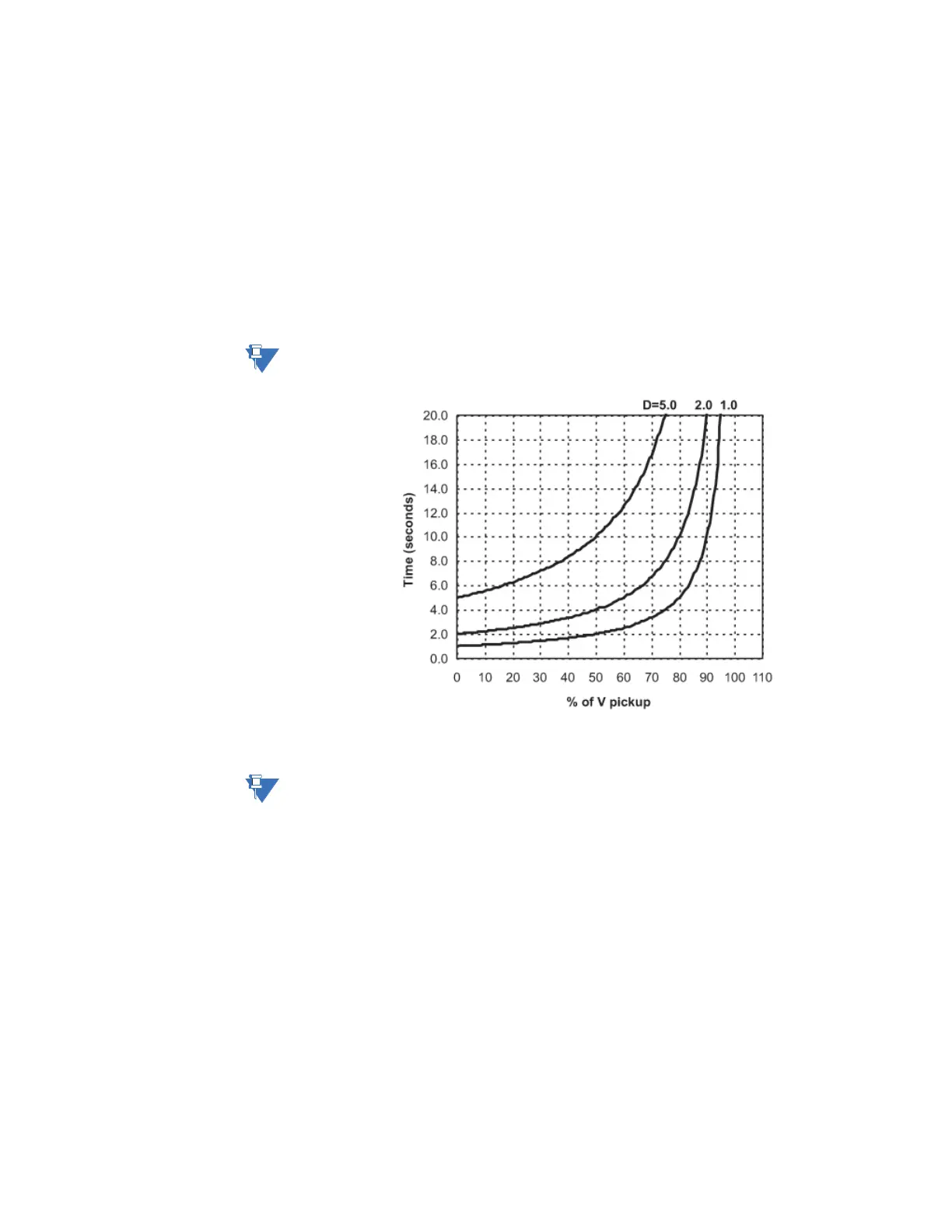
Undervoltage Curves The undervoltage elements can be programmed to have an inverse time delay
characteristic. The undervoltage delay setpoint defines a family of curves as shown below.
The operating time is given by:
T = D/(1 - V/V
pkp
)
Where:
T = Operating Time
D = Undervoltage Pickup Time Delay setpoint (for D = 0.00 operates instantaneously)
V = Voltage as a fraction of the nominal VT Secondary Voltage
V
pkp
= Undervoltage Pickup Level
The element resets instantaneously if the applied voltage exceeds the dropout voltage. The
delay setting selects the minimum operating time of the phase undervoltage.
NOTE:
At 0% of Pickup, the operating time equals the Undervoltage Pickup Time Delay setpoint.
Figure 4-72: Inverse Time Undervoltage Curves
If FlexCurves are selected, the operating time determined based on following equation:
T= Flexcurve (V
pkp
/ V)
NOTE:
FlexCurve reverses the ratio of voltages. The ratio of set pickup value to the measured
voltage.
Example: For a Pickup set to 0.9 x VT, when the measured voltage is 0.82 x VT, the ratio
would be 0.9/0.8 = 1.1, therefore in the FlexCurve, the corresponding Trip time setting entry
is at 1.1 x PKP (not at 0.82 x PKP). On the other hand, when the measured voltage is 1 x VT,
the ratio is 0.9/1 = 0.9, therefore, in the FlexCurve, the corresponding Reset time entry is at
0.9 x PKP.