GEr-861518
DRAWOUT
BREAKERS
GENERAL
Drawout
breakers
are
manufactured
in four different
styles, identified
in Table
2
by
the
mounting code
letters
None,
A, B & C.
The
"no-letter"
models are
used
in
General
Electric's AKD Switchgear.
Code
A
breakers
were later
intro-
duced with
AKD-5 Switchgear
and feature closed-door
draw-
out ooeration.
Code
B breakers
provide
an alternate closed-
door
drawout arrangement
with
the stationary element
furnished
as a
preassembled
"substructure".
Code C
breakers are exclusively
for
AKD-6 Switchgear;
they employ
the Code
A drawout
mechanism but have
finger-type
primary
studs
instead
of
tubular. The construction and operation
of
each of
these
drawout
styles
is
covered
under
respective
headings in the
following text.
As a
general
rule, breakers
of the same
drawout type,
voltage rating and ampere
frame size are
physically
inter-
changeable.
In
addition,
to be electrically
interchangeable
with respect to secondary and control circults,
they must
have duplicate
wiring.
The degree
of interchangeability
and
the
mechanisms
for
controlling
it are discussed separately
on
page
1
7.
NOTE:
The four
drawout
types are mutually
non-
interchangeable; before attempting to
insert a
breaker,
verify that the
breaker
model matches the
compartment.
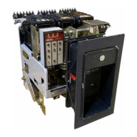
No CODE LETTER
(AKD
SWITCHGEAR)
(Fig.
1)
These
"no-lette/'
AKR-75/'l
00
models
are replacements
for their
AK-75 and AK-100
predecessors
in AKD switchgear.
The racking mechanism is
breaker-mounted and the
breakers are bolted to
a
roller-mounted
tray
in
an arrange-
ment
similar to the B Type
(see
page
8). In addition to the
characteristics listed in
Table 1, the
AKD drawout has the
following
unique aspects:
1. There
are three
(3)
distinct drawout
positions
-
CON-
NECTED, TEST
and WITHDRAWN.
2. Racking
travel
occurs
only
between the CONNECTED
position
and a
point
just
short
of
reaching
the TEST
position.
3. The
compartment
door must
be open
during racking.
Breaker
Insertion
(AKD
Type)
1. Prior
to lifting
a breaker to its intended
compartment
location,
observe the following
precautions:
a.
Check the
compartment
to insure
that
it
is free
of
foreign
objects.
b.
Verify
that
the breaker is
the
correct type for
that
compartment.
c.
Insure
that the breaker
ls OPEN.
d. Apply
athin, fresh
coat of
D50HD38
lubricantto
the
b
re
ake r's
p
ri m
ary di sco n n
ects.
e.
lnsure
that
the racking
cams on
the breaker
are
correctly
positioned
for initial
engagement
with
the
pins
in
the compartment.
To
do this, insert
the
rack-
ing
handle
and rotate
it fully
clockwise.
t. lf
a compartment
contains
a keylock,
it will
not ac'
cept
the AKR-751100
replacement
breakers
as
re-
ceived.
The AKR drawout
mechanism
differs
from
that of
its
predecessor
AK
model, causing
the
AKR
breaker
to mechanically
interfere
with the
keylock
during
breaker
insertion.
To remedy
this
it will be
necessary
to relocate
the keylock
using new
mount-
ing hardware
included as a
modification
kit. So al-
tered, the compartment
accepts both
AK and AKR
types.
2. Using a suitable
lifting mechanism and spreader
rig,
position
lifting hooks at the
cutout notches
in the top
wrap-
around
f rames of the breaker.
Exercise care to avoid
damage
to
the control
wiring.
3. Open the compartment.door.
Keeping the
rollout tray
positioned
inside
the compartment,
raise the breaker above
the elevation
of the tray.
4.
Depress the
test
position
stop lever and
pull
the tray all
the
way out to
its WITHDRAWN
position.
5. Lower the
breaker over the tray until
it is about one-
half inch above the two dowel
pins
on
the
tray.
Push the
breaker back
into
the comoartment
until the rear bottom
flange of the breaker
rests
against the
guides
behind the
dowel oins.
6. Slowly
lower and
guide
the breaker onto
the tray so
the holes
in
the rear
flange fit
over
the two dowel
pins.
When
correctly
positioned
on
the
dowel
pins,
the
breaker's
rear and
side
bottom
flanges will rest firmly on the tray.
7.
Secure the breakerto the tray by inserting
and
tighten-
ing two-s/e inch hex-head
screws into the front holes of its
side
flanges.
8.
lf
the breaker is a manually
operated
type,
push
it into
the
compartment until the TEST
position
stop engages,
preventing
further
travel. The breaker is
now
in
the
TEST
position.
lf
the breaker is
electrically
operated,
push
it into the
compartment
until the spring
discharge
stop
is
encountered.
Release
this
by depressing
the
"spring
discharge" lever
on the
bottom
of the breaker
(see
fig.
1), then
continue
pushing
the
breaker
into
the
compartment
until the TEST
position
stop
engages.
NOTE:A
sprlng
discharge
stopwill not
be
presentin
some
AKD-type
compartments
originally furnished
for
electrically
operated AK-75
and AK-100 breakers
of the
non-quick-close
type.
9. Depress
the
TEST
position
stop lever
and
push
the
breakerfarther
intothe
compartment
until
the outersurfaces
of
the racking
cams
butt against
the racking
pins
in the housing.
10. Insert
the racking
handle
(673D0500-636-05)
on the
jackscrew
shaft at the
upper
right
side
of
the
breaker. Rotate
it
clockwise
until the
jackscrew
comes
to
a
solid
stop. The
breaker is
now
in the
CONNECTED
oosition.
5
 Loading...