N07E: These instructions do not coverall
installations. However, the typical installation will be
to secure the installation plate to wall studs 16” apart.
Itis recommended that a stud finder be used to
locate the wall studs.
El
El
El
E
Measure the wall and mark the centerline. It is
also important to use caution concerning the
location of the installation plate-routing of
the tig to power outlets is through the walls
typically. Drilling the hole through the wall for
piping connections must be done safely.
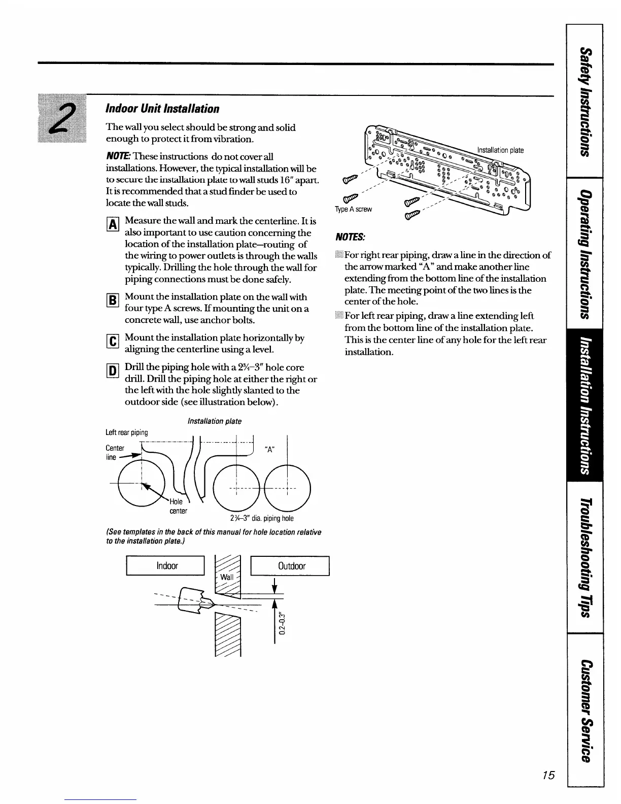
Mount the installation plate on the wall with
four type A screws. If mounting the unit on a
concrete wall, use anchor bolts.
Mount the installation plate horizontally by
aligning the centerline using a level.
Drill the piping hole with a 2%–3” hole core
drill. Drill the piping hole at either the right or
the left with the hole slightly slanted to b-e
outdoor side (see illustration below).
Installation plate
Left rear piping
. . !,
--.-. -.--. -.--1 1... ..-. -.-J -.J I
center
2%–3” dia. piping hole
(See templates in the back of this manual for hole location relative
to the installation plate.)
:door
I
Type A screw
NOIES:
‘ For right rear piping, draw a line in the direction of
the arrow marked “A” and make another line
extending from the bottom line of the installation
plate. The meeting point of the two lines is the
center of the hole.
For left rear piping, draw a line extending left
from the bottom line of the installation plate.
This is the centerline of any hole for the left rear
installation.
+~- ‘---- T.
75