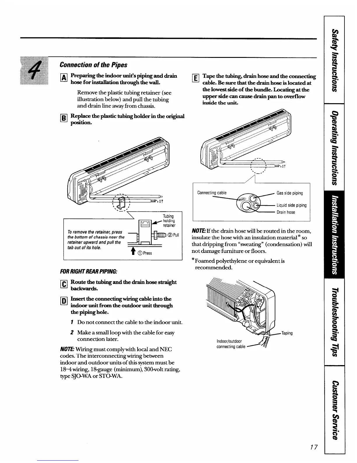
Preparingtheindoor unit’spipingand drain
hose forinstaUationthroughthewall.
Remove the plastic tubing retainer (see
illustration below) and pull the tubing
and drain line awayfrom chassis.
Replaee theplastictubingholder in the original
thelowestside of thebundle. Locating atthe
upper side cancausedrainpanto ove%low
insidethe unk
El
—
pcksition.
-----
To remove the retaine~ press
the bottom of chassis near the
@
Pull
retainer upward and pull the
J I
tab out of its hole.
r
❑
El
Route the tubingand thedrainhose straight
backwards.
Insertthe connectingwiringcableinto the
indoor unitfrom the outdoor unitthrough
thepiping hole.
1 Do not connect the cable to the indoor unit.
2 Make a small loop with the cable for easy
connection later.
N07E: Wtig must comply with local and NEC
codes. The interconnecting tig between
indoor and outdoor units of this system must be
18-4 wiring, 18-gauge (minim Urn),3oo-volt mting,
type SJO-WA or STOWA.
.
‘
Connecting cable
=@!!?!E;;;ng
N07E: If the drain hose will be routed in the room,
insulate the hose with an insulation material* so
that dripping from “sweating” (condensation) will
not damage fi.wniture or floors.
*Foamed polyethylene or equivalent is
recommended.
Indoor/outdoor
4
connecting cable ~
Taping