31-5000560 Rev. 5 19
Installation Instructions
Model:
ASH218JCDDA
ASH324JCDDA
Model:
ASH220NCDDA
ASH324NCDDA
ASH436JCDDA
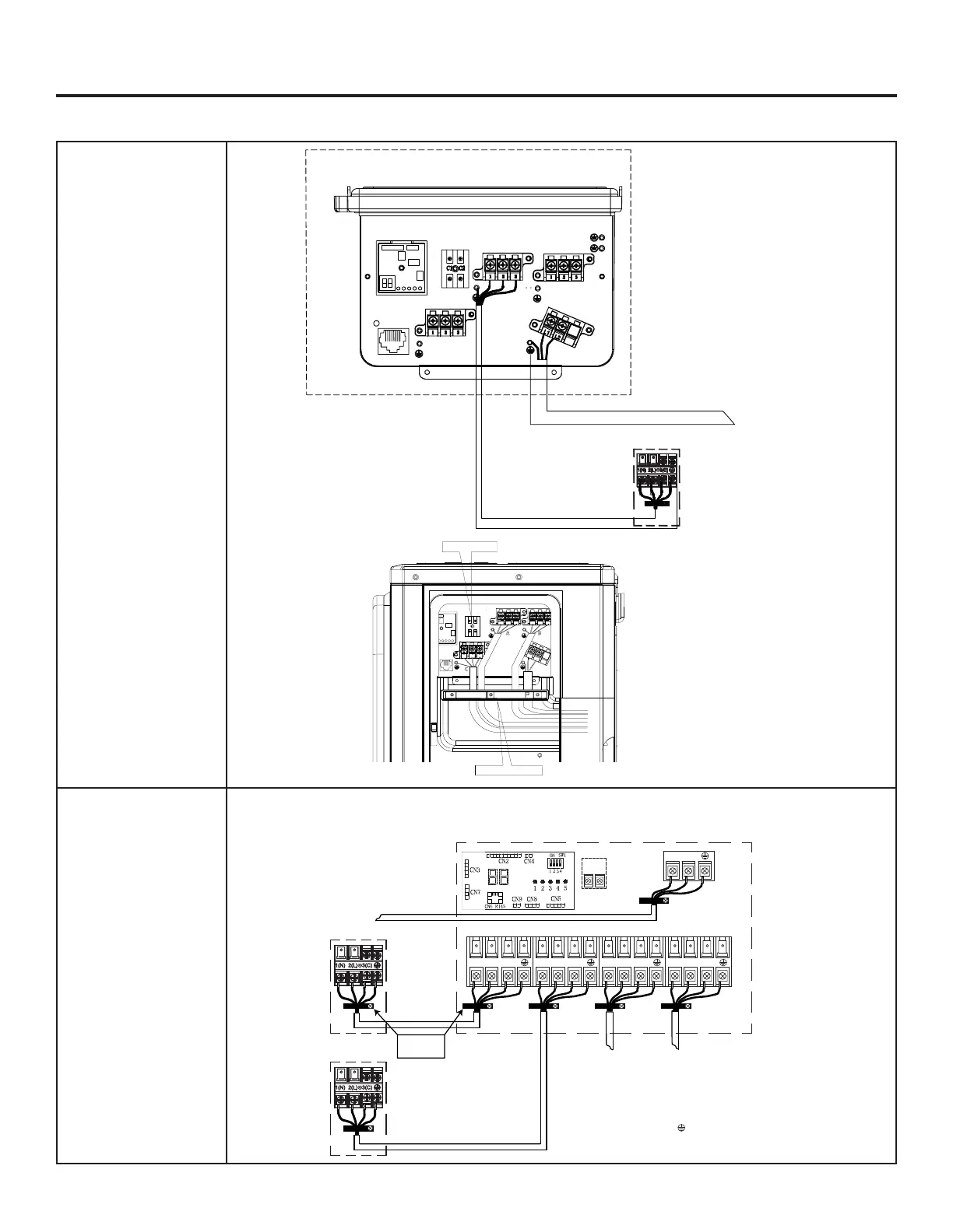
Step 3 - Installation of the Outdoor Unit (Cont.)
A
B
C
Suggested Colors:
L1=White
L2=Black
L3=Red
Ground= Solid Green
or Green-Yellow
Power Wiring
To Service Disconnect
208/230 Volt Supply. L1 to L1. L2 to L2.
Outdoor Unit
Indoor Unit A
Outdoor unit
Power Wiring
3
2
1
)
(
N
)
(L
)
(
C
2
1
)
(
N
)
(
L
Indoor unit A
Control Wiring
4 Wire - 14 AWG
Stranded
43
To Service Disconnect
1
2
3
=White
=Black
=Red
=Green
ABCD
Sugested Colors
230 Volt Supply. 1 to L1, 2 to L2.
Indoor unit B Indoor unit C Indoor unit D
3
2
1
)
(
N
)
(L
)
(
C
3
2
1
)
(
N
)
(L
)
(
C
3
2
1
)
(
N
)
(L
)
(
C
Strain Relief
Brackets
Power Wiring
To Service Disconnect
208/230 Volt Supply. L1 to L1. L2 to L2.
Strain Relief Brackets
C1 C2
1 2 3
1 2 3
L1 L2
1 2 3
Central Control



 To Next Page