20 31-5000560 Rev. 5
Installation Instructions
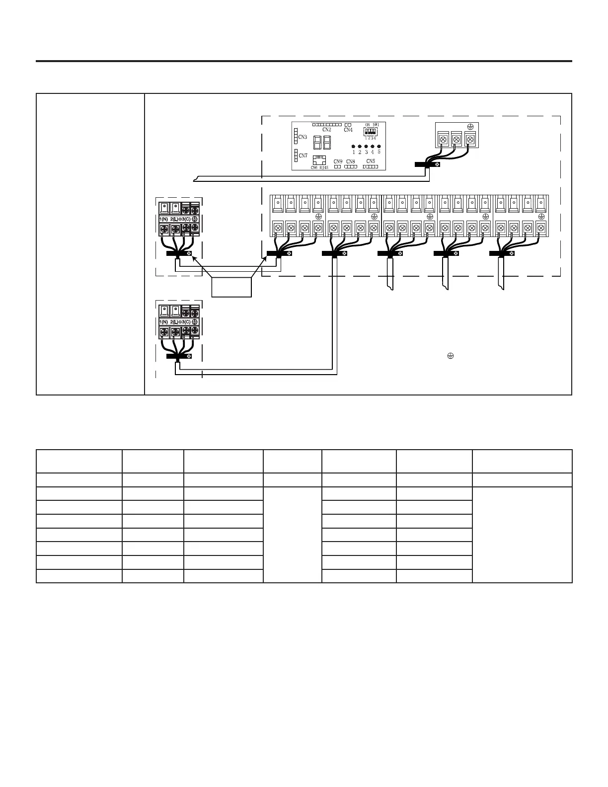
Step 3 - Installation of the Outdoor Unit (Cont.)
Model:
ASH436NCDDA
ASH542JCDDA
Power Wiring
3
2
1
)
(
N
)
(L
)
(
C
2
1
)
(
N
)
(
L
Indoor unit A
Control Wiring
4 Wire - 14 AWG
Stranded
To Service Disconnect
1
2
3
=White
=Black
=Red
=Green
ABCD
Sugested Colors
230 Volt Supply. 1 to L1, 2 to L2.
Indoor unit B Indoor unit C Indoor unit D
3
2
1
)
(
N
)
(L
)
(
C
3
2
1
)
(
N
)
(L
)
(
C
3
2
1
)
(
N
)
(L
)
(
C
Strain Relief
Brackets
E
3
2
1
)
(
N
)
(L
)
(
C
Model Number
Factory
Charge
Total Pipe Length
of factory charge
Additional
charge rule
Branch Maximum
pipe length
System Maximum
pipe length
Minimum pipe length
Unit oz ft oz/ft ft ft ft
ASH218JCDDA 60 50
0.2
65 98
10’ per indoor
ASH324JCDDA 67 100 82 197
ASH436JCDDA 90 131 82 230
ASH220NCDDA 69 66 82 165
ASH324NCDDA 82 100 82 197
ASH436NCDDA 102 131 82 230
ASH542JCDDA 113 164 82 262
Refrigerant Charge and Pipe Length Information



 To Next Page