EasyManua.ls Logo

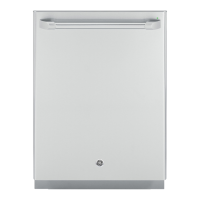
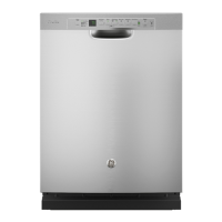
GE CDT865SxJ0 Series User Manual

GE CDT865SxJ0 Series
95 pages
To Next Page IconTo Next Page
Page #1 background imageLoading...
Page #1 background image
GE Appliances
Louisville, Kentucky 40225
31-9256
Technical Service Guide
June 2016
GE Appliances
CDT835SxJ0xx
CDT865SxJ0xx
PDF820SxJ0xx
PDT825SxJ0xx
PDT845SxJ0xx
PDT846SxJ0xx
PDT855SxJ0xx
ZDT915SxJ0xx
ZDT975SxJ0xx
2016 Stainless Steel Tub Dishwasher

Table of Contents

Questions and Answers:

GE CDT865SxJ0 Series Specifications

General IconGeneral
TypeBuilt-In
Capacity16 place settings
Water Filtration SystemYes
Sanitize CycleYes
ENERGY STAR® QualifiedYes
Soil SensorYes
Stainless Steel TubYes
Delay StartYes
Water HeaterYes

Summary

Safety Information

Safety Requirements

Lockout/Tagout (LOTO) 6 Step Process

Mandatory 6-step process for safety before disassembly.

Electrical Specifications

AC Voltage Specifications

Details voltage, amp, LRA, GPM for circulation and drain pumps.

DC Voltage Specifications

Lists DC voltages for main control, UI, inverter, and various components.

Operation and Cycle Information

Target Temperatures

Exposed Heater Target/Max Temperature Limits

Table showing target temperatures for cycles with an exposed heater.

Hidden Heater Target/Max Temperature Limits

Table showing target temperatures for cycles with a hidden heater.

Cycle Details

Cycle Algorithm Comparisons

Details fill, circ, and drain times for various cycles and wash zones.

Troubleshooting

Service LED Diagnostics

Location and purpose of the Service LED for diagnosis.

Flashing Lights and Indicators

Interpretation of flashing LEDs or displays as fault conditions.

Will Not Start Issues

Diagnosing and resolving issues when the dishwasher does not start.

Tub and Structure

Junction Box and House Wiring Connection

Details location and connection of the junction box for house voltage.

Tub and Structure (Continued)

Door Latch/Switch Assembly Replacement

Procedures for replacing the door latch and switch assembly.

Latch Switch Diagnosis

How to diagnose the latch switch using Consumer Error Mode or an ohm meter.

Door

Door Removal Procedure

Detailed steps for removing the dishwasher door.

Control Interface Components

Front Control UI, Light Pipe and Buttons

Steps for accessing and removing UI, light pipe, and buttons.

Top Control Panel, UI, Light Pipe and Buttons

Details on accessing UI, light pipe, and buttons for top control models.

Control Interface Components (Continued)

Accessing UI, Control Covers, Buttons and Light Pipe

Steps to access UI, covers, buttons, and light pipe from the control panel.

Detergent Dispenser

Detergent Module Operation and Function

Explains solenoid operation, rinse agent dispenser, and level sensor.

Diagnosing the Detergent Module

Steps to diagnose the detergent module using Service Mode.

Sensors and Floor Protection

Rinse Aid Sensor Operation

Explains how the sensor detects rinse aid level using voltage signals.

Diagnosing the Rinse Aid Sensor

Procedure to check sensor operation and LED indicators.

Sump Module

Sump Module Removal Instructions

Detailed steps for removing the sump module assembly.

Sump Module (Continued)

Sump Module Latch and Hose Disconnection

Details on releasing sump latches and disconnecting hoses.

Sump Gasket and Installation

Sump Module Reassembly Steps

Instructions for reconnecting wiring and aligning the sump module.

Electronic Controls

Main Control Board Overview

Location and function of the main control board and its outputs.

CSM (Current Sense Module) Function

Explains the CSM's role as a protective device against ground leakage.

Electronic Controls (Continued)

Top Control LCD Model Fault Codes

Table listing fault codes, descriptions, and causes for LCD models.

Main Control Board CSM

CSM Diagnostics Flowchart

Visual guide for diagnosing CSM trips and related issues.

Service Mode

Entering Service Mode Procedure

Steps to enter Service Mode and its effect on CSM.

Service Mode Load Tests (PDF/PDT Models)

Table of LED blink codes and load tests for specific models.

Service Mode Load Tests (Other Models)

Table of load tests for other specified models in Service Mode.

Diagnosing Electronic Control Boards

Main Control Diagnostics (Service LED)

Interprets Service LED blink patterns to diagnose control board status.

Main Control Board Access

UI Diagnostics

User Interface (UI) Diagnostic Checks

Describes checks for UI operation, voltage, and harness issues.

Main Control to UI Voltage Checks

Details voltage checks from main control to UI for diagnosis.

Inverter Control Board

Inverter Safety Precautions

Warns about high voltage and recommends safety gear when working with the inverter.

Inverter and Motor Diagnostics

Accessing Dishwasher Fault Codes

How to access and interpret fault codes for inverter and motor issues.

Inverter and Motor Fault Code Table

Lists fault codes, descriptions, and causes for inverter/motor problems.

Inverter and Motor Diagnostics (Continued)

Circulation and/or Drain Motor Not Operating Flowchart

Diagnostic flowchart for troubleshooting motor operation issues.

Accessing Inverter Fault Codes

How to interpret inverter service LED blink patterns for faults.

TCO and Motor Winding Schematics

WiFi Connect (Continued)

Fill System

Fill System Diagnostics

Dishwasher Not Filling Diagnostic Flowchart

Flowchart for troubleshooting when the dishwasher does not fill.

Circulation System

Circulation System Operation Overview

How water is filtered and directed to spray arms via the diverter.

Circulation System Diagnostics

Using the Clear Door Diagnostic Tool

How to use the clear door to view wash zones and diagnose issues.

Clear Door Diagnostic Tool Usage Steps

Step-by-step guide for using the clear door tool.

Circulation System Diagnostics (Continued)

No Circulation Troubleshooting Flowchart

Diagnostic flowchart for troubleshooting models with no circulation.

Filtration

Circulation Motor and Pump Assembly

Circulation Pump Motor Assembly Removal

Steps for removing the circulation pump motor assembly.

Hidden Heater Diagnostics

Hidden Heater Diagnostics and Testing

Procedures for testing the hidden heater resistance and voltage.

Pressure Diverter

Pressure Diverter Function and Operation

Explains how the diverter alternates water flow to spray arms.

Pressure Diverter (Continued)

Pressure Diverter (Continued)

Diverter Removal Procedure

Steps for removing the diverter from the sump assembly.

Turbidity Sensor and Thermistor

Turbidity Sensor Operation

Explains how the sensor measures water turbidity to adjust cycles.

Thermistor Function and Location

Describes the thermistor's role in monitoring water temperature.

Thermistor Specifications

Provides voltage, resistance, and temperature data for the thermistor.

Turbidity Sensor (Continued)

Conduits and Spray Arms

Lower Spray Arm and Conduit

Main Conduit

Middle Spray Arm

Drain System

Drain System Operation and Components

Describes drain pump operation, hose connections, and check valve.

Drain System (Continued)

Diagnostics for Single Speed Drain Pump

Flowchart and checks for single speed drain pump issues.

Drain System (Continued)

Drain Pump Removal or Replacement

Steps to remove and replace the drain pump.

Dry System

Dry System Introduction and Operation

Explains how heat and air circulation achieve drying.

Dry System (Continued)

Heat Element Diagnostics

Flowchart and resistance checks for troubleshooting the heat element.

Dry System (Continued)

Heat Element Removal Procedures

Two methods for removing the heat element.

Power Dry Forced Air

Power Dry Forced Air (Continued)

Schematics

Schematics (Continued)

ZDT Model Schematics

Related product manuals