CHAPTER 2: MODBUS COMMUNICATION MODBUS MEMORY MAP
D90
PLUS
LINE DISTANCE PROTECTION SYSTEM – COMMUNICATIONS GUIDE 9
values for the previous Address lines incremented by 1. An address value of “0” in the initial
register means "none" and values of “0” displays for all registers. Different address values
can be entered as required in any of the register positions.
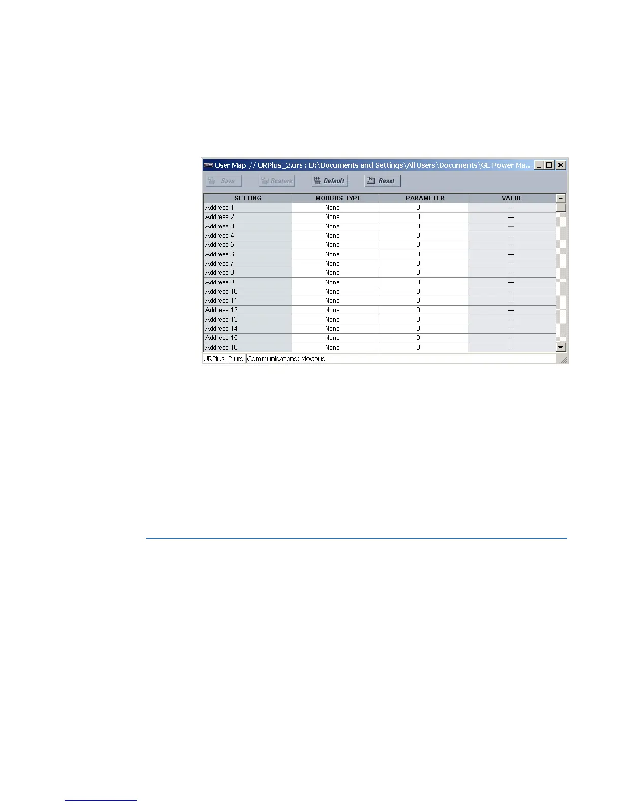
Select the Settings > Communications > Modbus > User Map menu to open the Modbus
user map configuration window.
Figure 2: Modbus user map configuration settings
The following settings are available for each of the 256 registers.
Modbus Type
Range: None, Settings, Actuals
Default: None
This setting indicates if the Modbus user map address represents a setting or an actual
value.
Parameter
Range: Modbus memory map address in decimal representation
Default: 0
This setting represents the value of the programmed Modbus memory map address.
Modbus memory map
The table outlines the user-accessible features of the D90
Plus
Modbus memory map. Those
present depend on order code.
The memory map is also viewable in a web browser. In the browser, enter the IP address of
the D90
Plus
.
The memory map is also provided as a .ini file. See the SYS_ModbusMemoryMap.ini file
provided on the CD.
See the Modbus data formats section that follows for details on the Format codes for each
register, for example F001.
 Loading...


