2-
30
DGP Digital Generator Protection System GE Power Management
2.3 PROTECTION FUNCTION SETTINGS 2 CALCULATION OF SETTINGS
2
phases for different phase designations (Setting 109:
PHASE
) and VT connections (Setting 116:
VT
CONN
).
3. Reset time: Linear reset with maximum time =
RESET
setting (Setting 1409).
This function should be set with a safe margin below the excitation capability of the generator or step-up
transformer, whichever is lower. The following example is based on the traditional criteria of 45 seconds
operating time at V/Hz from 1.1 to 1.18 per unit. However, actual excitation capability curves should be
obtained for the generator and the transformer to take full advantage of the inverse characteristic of this
function. Setting 1409:
RESET
should be set to match the cooling characteristic of the protected equip-
ment (if known). If the reset characteristic is not available, a setting in the range of 0 to 50 seconds may be
used.
For the sample generator system, using CURVE #4 (definite time) and operating time of 45 seconds:
set
INV PU
= 1.10 per unit
set
TIME FAC
= 45 seconds
set
INST PU
= 1.18 per unit
set
TL7
= 2 seconds
set
RESET
= 30 seconds
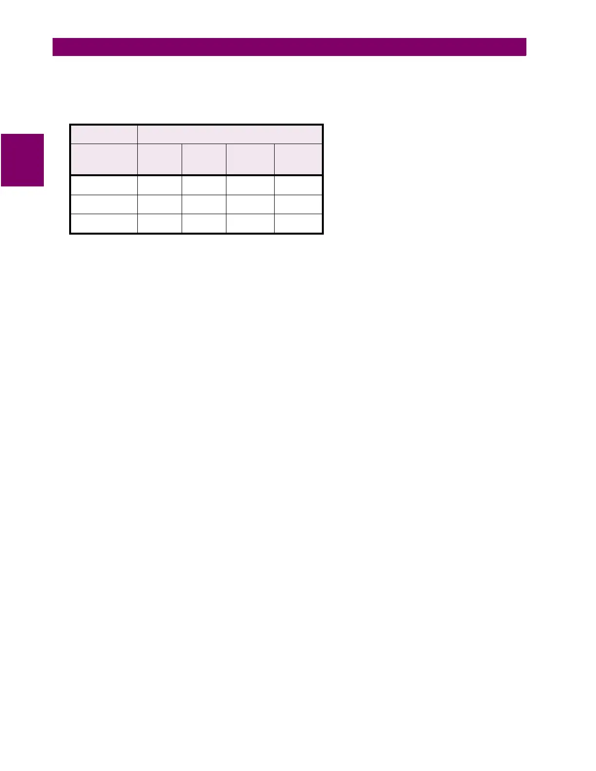
Table 2–3: 24A VOLTAGES
PHASE VOLTAGES
PHASE
→
VT
→
ABC
WYE
ABC
DELTA
ACB
WYE
ACB
DELTA
A
V
A
V
AB
V
A
V
AB
B
V
B
V
BC
V
B
V
BC
C
V
C
V
CA
V
C
V
CA



 To Next Page