GE Power Management DGP Digital Generator Protection System 3-
3
3 HARDWARE DESCRIPTION 3.1 CASE ASSEMBLY
3
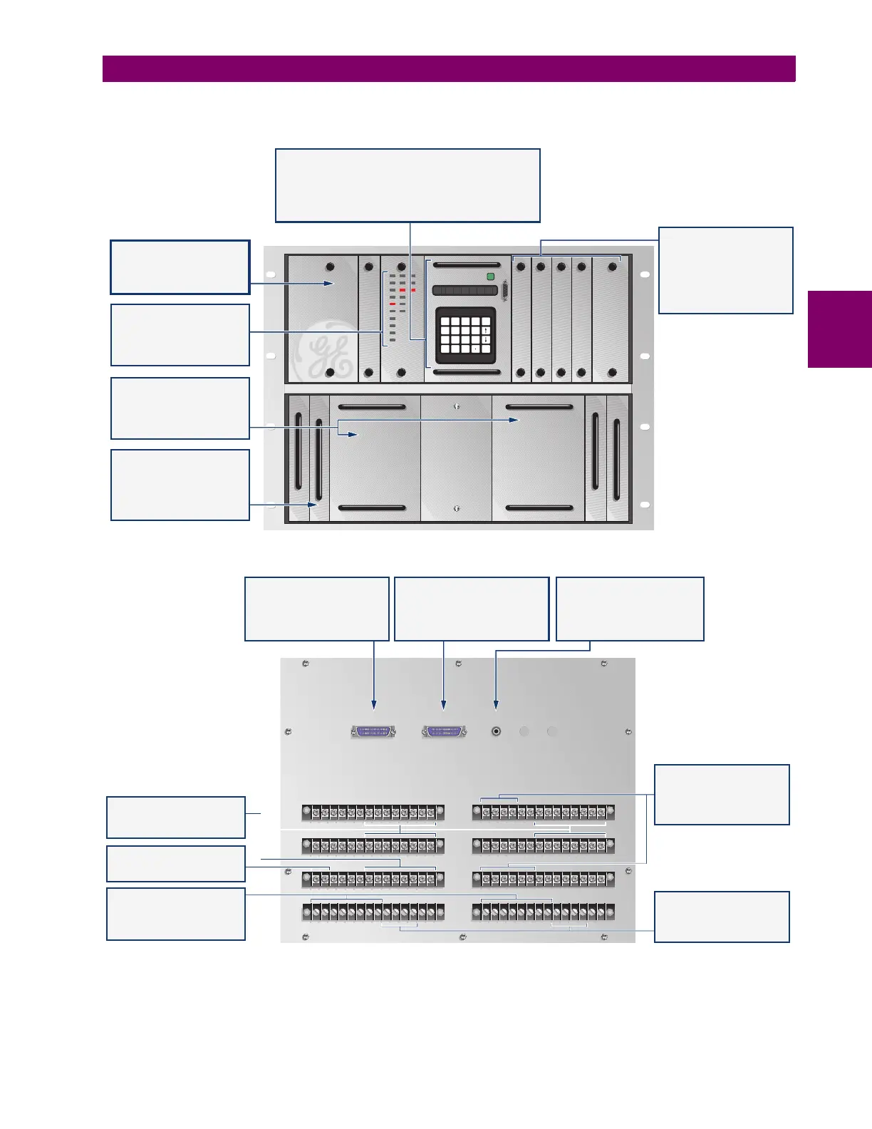
Figure 3–2: FRONT AND REAR VIEW
704752A8.CDR
1 115
2 216
17
2828
2727 1313
17
1212
16
1111
15
1414
DIT101
57A
51V-A
24A
40G1
64G1
81-U
32
59
46
VTFF
57B
51V-B
24B
40G2
64G2
81-O
57C
51V-C
24C
GREEN: PROTECTION ON
RED: CHECK STATUS
RATINGS
IN 5 AMP
VN 100/140 VOLTS
FREQ 50/60 Hz
RATINGS
IN 5 AMP
VN 100/140 VOLTS
FREQ 50/60 Hz
MMI301 SSP301 ANI301 DAP201 DSP401
MMI301
F L T T YP E : B
SET
INF
ACT
END
1/V
4
7
PRT
2
5
8
0
3/N
6
9
CLR
ENT
PS1 PS2
TPM1 MGM781 MGM781 TPM2
DIT101 MMI301 SSP301 ANI301 DAP201 DSP401
PS1 PS2
PL-1 PL-2 PL-3
AG
AH
AE
AF
BE
BF
BG
BH
MAN MACHINE INTERFACE MODULE (MMI)
n
n
n
n
16 digit alpha-numeric LED display for fault report,
metering values, alarm messages, setting parameters, etc.
keypad includes 20 keys for user friendly
local interface with the DGP
dual color LED indicates relay status
RS232 port facilitates connection of lap-top PC
MODULES
System Processor (SSP),
Analog Interface (ANI),
Data Acquisition (DAP), &
Digital Signal Processor
(DSP) modules are plug-in
type for ease of maintenance
and trouble-shooting.
DIGITAL INPUT & TARGET
MODULE (DIT) LED targets
indicate ALL the fuctions
that operated during a
trip event
MAGNETIC MODULES
(MGM) Two identical
modules contain CT's, VT's,
output relays, etc. and are
interchangeable.
OPTIONAL TEST BLOCKS
facilitate injection of
analog input signals and
monitoring of DGP outputs
for test purpose without
disturbing field wiring.
POWER SUPPLY MODULES
are located behind the
cover plate. Module PS2
is optional
RS232 PLUG (PL-1)
provides connection to modem
for remote communications
or an interface to station
integration system.
OPTIONAL SERIAL PORT (PL-2)
Can be used to connect a
printer for automatic/manual
printout of data or a Contact
Expansion Unit DEC1000.
OPTIONAL PLUG (PL-3)
Available for IRIG-B signal input
to synchronize the DGP internal
clock to a common reference
clock e.g. GPS receiver.
VT INPUTS:
n
n
3 phase vt inputs,
wye or delta
1 neutral vt input
DIGITAL INPUTS:
n
n
3 configurable contact
inputs
3 predefined contact
inputs
CONTROL POWER
DC control power input
CT INPUTS
n
n
n
6 phase CT inputs
1 residual CT input
1 residual/neutral CT input
OUTPUT RELAY CONTACTS
n
n
8 configurable relays
8 predefined relays



 To Next Page