Do you have a question about the GE druck dpi 104 and is the answer not in the manual?
Emphasizes reading all safety procedures, instructions, and user guides before operating the instrument.
Explains CE compliance, warning symbols, and proper product disposal procedures.
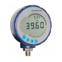
Identifies and describes the buttons and connectors of the DPI 104 instrument based on Figure A1.
Explains how to select one of the 11 available pressure measurement units for the display.
Details how to use the tare function to zero the displayed pressure value, crucial for accurate readings.
Describes how to monitor and record the highest and lowest pressure values encountered.
Explains how to measure the performance and hysteresis of an external pressure switch.
Outlines steps for calibration, including access codes and selecting calibration types (CO, C2, V2).
Guides users on setting low/high pressure alarm limits based on Full Scale Output (FSO).
Explains how to configure the voltage output (0.05-5V) for external systems in P-V or US modes.
Details how to adjust the Vout scale factor for accurate voltage output calculations with external regulators.
Describes how to configure the automatic power-off timer to conserve battery life.
Explains how to set a lock code to prevent accidental changes to configuration settings.
How to set the rate at which the DPI 104 takes pressure samples from the internal sensor.
How to read pressure from an external IDOS UPM, noting accessory requirements.
How to define custom ranges for analog display, % indication, and alarms using FSO registers.
Step-by-step procedure for installing or replacing the battery, emphasizing GE-specified parts.
Guidance on selecting a safe and optimal installation position for the instrument, avoiding stress.
Information on the 11 available units for pressure measurement and related setup references.
Explains the tare function to adjust the displayed pressure value and lists permitted tare values.
Detailed steps for setting a tare value (tA), display indications, and error code interactions.
Describes how tare setting interacts with lock, alarm, and Vout functions, including display behavior.
Notes on how tare setting affects the indication when FSO Low/High values are used.
Step-by-step guide to setting low/high alarm values and accepting/canceling changes.
Example calculation for Vout in P-V mode based on pressure and FSO.
Explains Vout calculation in US mode using Vout register and scale factor.
Steps to connect and configure the Vout function, including diagrams.
Step-by-step guide to setting FSO low and high register values within permitted ranges.
Instructions for cleaning the instrument case and checking for damage to threads and o-rings.
Guidance on returning the instrument for repair and proper electronic waste disposal.
Details required calibration equipment and the need for a stable temperature environment.
Outlines the general procedure for calibration, including connecting equipment and setting access codes.
Details the displays and steps for setting the first calibration point (P1) for pressure calibration.
Details the displays and steps for setting the second calibration point (P2) for pressure calibration.
Details the displays and steps for setting the first calibration point (P1) for voltage calibration.
Details the displays and steps for setting the second calibration point (P2) for voltage calibration.
Lists display type, safety standards, power supply requirements, and EMC compliance.
Details operating and storage temperatures, humidity, vibration, altitude, and pollution degree.
Covers switch input, alarm output, analog output, temperature coefficient, and battery life.
Includes information on case materials, approvals (CE marking), size, and weight.
Table detailing pressure ranges, types, resolutions, maximum working pressures, and media compatibility notes.
Specifies the accuracy for different pressure ranges and lists the available measurement units and connection types.
| Brand | GE |
|---|---|
| Model | druck dpi 104 |
| Category | Touch Panel |
| Language | English |