Do you have a question about the GE EntelliGuard and is the answer not in the manual?
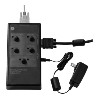
Powers up the trip unit; indicated by a green Power LED. A red Battery Low LED signals battery replacement.
Causes the breaker to trip. Associated red LED indicates when the switch is active.
Temporarily disables the trip unit's GF protection. The GF switch and LED indicate its state.
Puts the trip unit into a testing mode. Current shall not be applied to the breaker in this state.
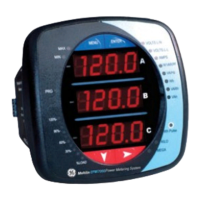
Enabled in Test Mode; displays ~100A on each current phase via the trip unit's METER menu.
Describes the 15-pin trip unit cable and 9-pin serial communication cable for connecting the test kit.
Details powering the trip unit via the test kit or external 24V source for testing.
Verifies breaker tripping mechanism by firing the flux shifter via the Trip Breaker button.
Allows testing of single-phase breaker protection by temporarily disabling GF protection.
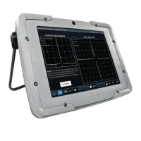
Enables testing of the trip unit's measurement circuitry by applying fixed voltage to sensing circuits.
| Brand | GE |
|---|---|
| Model | EntelliGuard |
| Category | Test Equipment |
| Language | English |