Installation Instructions
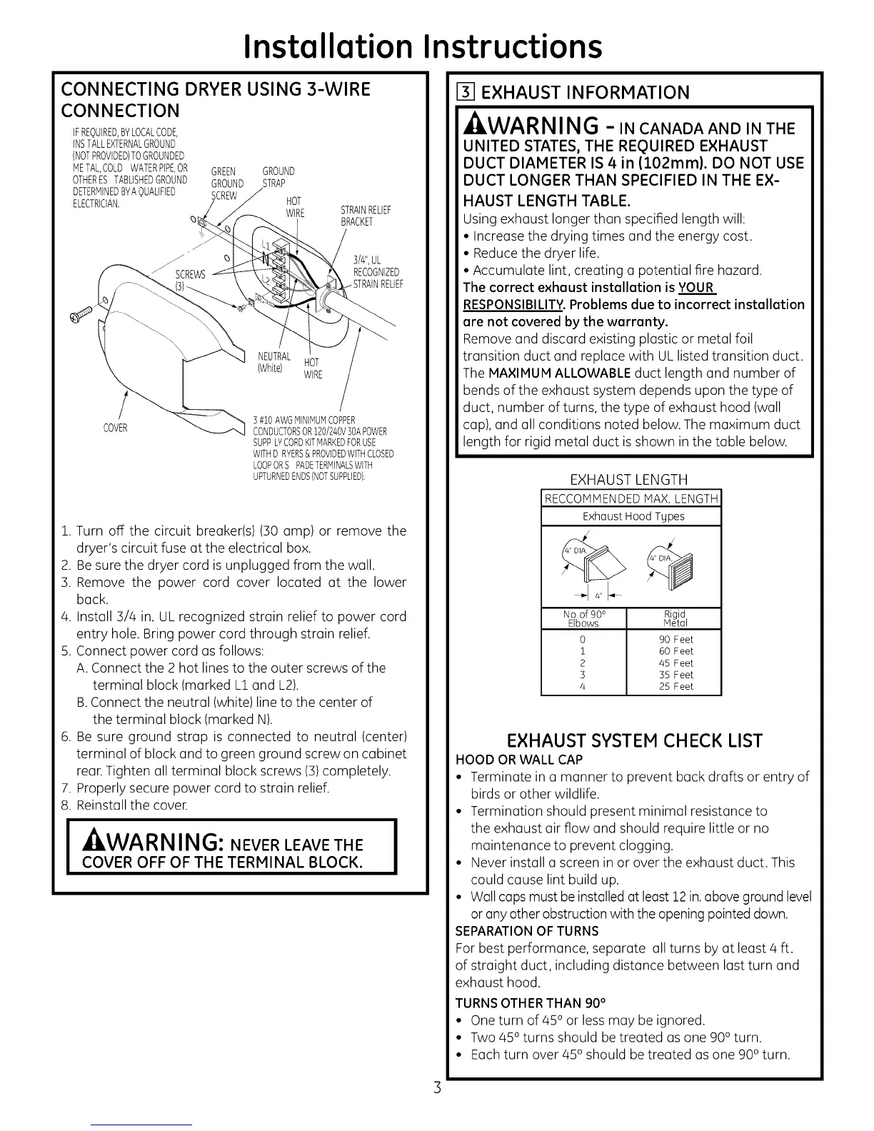
CONNECTING DRYER USING 3-WIRE
CONNECTION
IFREQUIRED,BYLOCALCODE,
INSTALLEXTERNALGROUND
(NOTPROVIDED)TOGROUNDED
METALCOLDWATERPIPE,OR
OTHERESTABLISHEDGROUND
DETERMINEDBYAQUALIFIED
ELECTRICIAN,
_5
GREEN GROUND
GROUND STRAP
SCREW HOT
WIRE
STRAINRELIEF
BRACKET
3/#',UL
RECOGNIZED
NEUTRAL
{White) HOT
WIRE
COVER
] #i0 AWGMINIMUMCOPPER
CONDUCTORSOR120/240V]OAPOWER
SUPPLYCORDKITMARKEDFORUSE
WITHD RVERS& PROVIDEDWITHCLOSED
LOOPORSPADETERMINALSWITH
UPTURNEDENDS(NOTSUPPLIED).
1. Turn off the circuit breaker(s) (30 amp) or remove the
dryer's circuit fuse at the electrical box.
2. Besure the dryer cord is unplugged from the wall.
3. Remove the power cord cover located at the lower
back.
4. Install 3/4 in. UL recognized strain relief to power cord
entry hole. Bring power cord through strain relief.
5. Connect power cord as follows:
A. Connect the 2 hot lines to the outer screws of the
terminal block (marked L] and L2).
B.Connect the neutral (white) line to the center of
the terminal block (marked N).
6. Be sure ground strap is connected to neutral (center)
terminal of block and to green ground screw on cabinet
rear.Tighten all terminal block screws (3)completely.
7. Properly secure power cord to strain relief.
8. Reinstall the cover.
I WARNING: NEVER LEAVE THE I
COVER OFF OF THE TERMINAL BLOCK.
131EXHAUST INFORMATION
,AWARNING -IN CANADAANDINTHE
UNITED STATES, THE REQUIRED EXHAUST
DUCT DIAMETER IS 4in (102ram). DO NOT USE
DUCT LONGER THAN SPECIFIED IN THE EX-
HAUST LENGTH TABLE.
Using exhaust longer than specified length will:
• Increase the drying times and the energy cost.
• Reduce the dryer life.
• Accumulate lint, creating a potential fire hazard.
The correct exhoust instollation is YOUR
RESPONSIBILITY.Problems due to incorrect installation
are not covered by the warranty.
Remove and discard existing plastic or metal foil
transition duct and replace with ULlisted transition duct.
The MAXIMUM ALLOWABLEduct length and number of
bends of the exhaust system depends upon the type of
duct, number of turns, the type of exhaust hood (wall
cap), and all conditions noted below. The maximum duct
length for rigid metal duct isshown in the table below.
EXHAUST LENGTH
RECCOMMENDED MAX. LENGTH
Exhaust Hood Types
No.of90 °
Elbows
0
i
2
3
4
Rigid
Meto
90 Feet
60 Feet
45 Feet
35 Feet
25 Feet
EXHAUST SYSTEM CHECK LIST
HOOD ORWALL CAP
• Terminate in a manner to prevent back drafts or entry of
birds or other wildlife.
• Termination should present minimal resistance to
the exhaust air flow and should require little or no
maintenance to prevent clogging.
• Never install a screen in or over the exhaust duct. This
could cause lint build up.
• Wall caps must be installed at least 12 in.above ground level
or anyother obstruction with the opening pointed down.
SEPARATIONOF TURNS
For best performance, separate all turns by at least 4 ft.
of straight duct, including distance between last turn and
exhaust hood.
TURNSOTHERTHAN 90°
• One turn of 450 or less may be ignored.
• Two 450 turns should be treated as one 900turn.
• Each turn over 450 should be treated as one 900 turn.
 Loading...