Do you have a question about the GE GFDR485GF and is the answer not in the manual?
Important notice regarding the intended user and limitations of the service guide.
Instructions for ensuring proper grounding after service procedures.
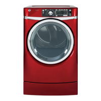
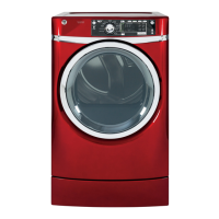
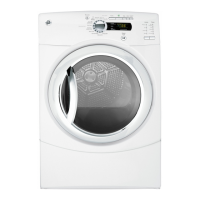
Diagrams and descriptions of the dryer's control panel buttons and cycles.
Details on choosing the appropriate dry cycle for different fabric types.
Steps to access the diagnostic service mode.
How to navigate and perform tests within the service mode.
Methods to safely exit the diagnostic service mode.
Table detailing error codes, conditions, and response actions.
Diagram showing component locations on the front of the dryer.
Diagram showing internal components after front panel removal.
Diagram showing component locations on the rear of the dryer.
Diagram showing internal components after rear panel removal.
Procedure for programming the model ID code into a new control board.
Details on the main control board's wiring and removal process.
Instructions for replacing the drive belt and removing the drum.
Details on the heater assembly and its removal process.
Explanation of how gas flows to the burner and the valve system.
Steps for gas conversion and safe removal of the gas valve.
General wiring diagram for electric dryer models.
| Brand | GE |
|---|---|
| Model | GFDR485GF |
| Type | Front Load |
| Fuel Type | Electric |
| Drying Technology | Sensor Dry |
| Number of Cycles | 12 |
| Steam Option | Yes |
| Energy Star Certified | Yes |
| Color | White |
| Wrinkle Care Option | Yes |
| Moisture Sensor | Yes |
| Weight | 130 lbs |
| Dry Cycles | Quick Dry |