44
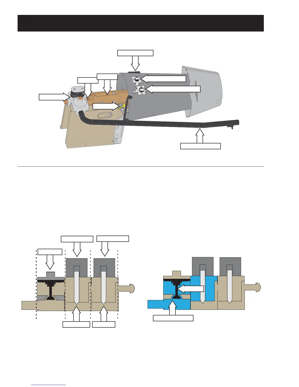
Gas Heating System
2UL¿FH
Gas Supply Pipe
Igniter
Burner
Gas Valve
Inlet Thermostat
High Limit Thermostat
Gas Flow
*DVÀRZWRWKHEXUQHULVFRQWUROOHGE\WKHJDVYDOYH
assembly. The gas valve assembly consists of a
regulator, safety valve, main valve and solenoids to
operate the gas valves. See below.
Gas Valve Block Diagram
Regulator
Safety Valve
Main Valve
Dual Solenoid
Single Solenoid
The dual solenoid consists of a safety coil and a
booster coil. To ensure safe operation, both coils
must be energized in order to open the safety valve.
As gas enters the gas valve assembly, the regulator
DQGVDIHW\YDOYHFKDPEHUV¿OOZLWKJDVDVVKRZQLQ
WKHVKDGHGDUHDLQWKH¿JXUHEHORZ
The regulator regulates gas pressure by moving an
actuator up and down as needed. When the gas
pressure goes too high, the excess pressure in the
regulator chamber forces the actuator to rise. This
FORVHVRȺWKHJDVHQWU\SRUW$VWKHJDVSUHVVXUH
lowers, the port opens back up.
Regulator and Safety Chamber
Actuator
Gas Entry Port
Flame Detector