Control Board
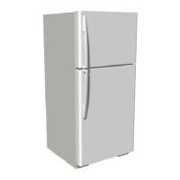
The electronics architecture for top mount 20 ft model consists of 1 electronic board. The control
board reads analog signal from thermistors and convert it to temperature and controls the Compresor
and Defrost heater for Refrigerator operation. It also has 2 door signals to create adaptive defrost. It
communicates to the display board by serial port.
a) Feeding 127VAC control card in the main connector.
b) Measure voltage at the output of voltage regulator on the control card:
The value should be 5 + / - 0.2 VDC at the output of regulator U3 (TP TP Vcc and GND).
Temperature Verification and start cutting
a) Feeding 127VAC control card in the main connector
b) Turn the potentiometer knob in position 5 (counterclockwise to clockwise).
the flat side of
the stem is at

 Loading...