– 35 –
trahCtnioPteSerutarepmeT
lortnoC
gnitteS
dooFhserF
tnemtrapmoC
rezeerF
tnemtrapmoC
dooFhserF
rotsimrehT
egnaRerutarepmeT
rotsimrehTrezeerF
egnaRerutarepmeT
muminiMmumixaMmuminiMmumixaM
0ffOffO
1F°44F°6F°34F°54F°1F°11
2F°04F°4F°93F°14F°1-F°9
3F°93F°3F°83F°04F°2-F°8
4F°83F°1F°73F°93F°4-F°6
5F°73F°0F°63F°83F°5-F°5
6F°63F°1-F°53F°73F°6-F°4
7F°53F°3-F°43F°63F°8-F°2
8F°53F°4-F°43F°63F°9-F°1
9F°43F°6-F°33F°53F°11-F°1-
Thermistors
This main control board uses input from 3 thermistors. These thermistors are located in the fresh
food section, the freezer section, and on the evaporator. The main control board monitors the
thermistors to determine the temperature in these areas of the unit and determines which
components to run and when to run them, based on this information.
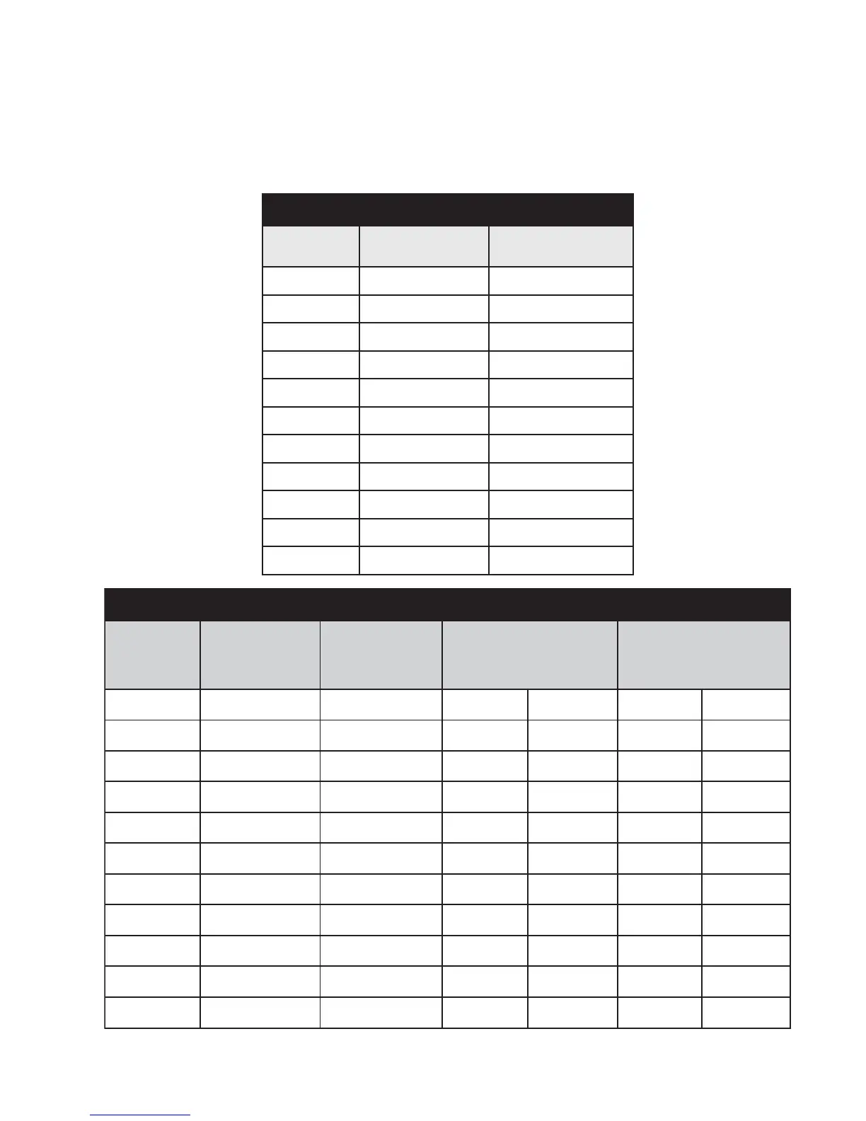
seulaVrotsimrehT
erutarepmeT
)C(seergeD
erutarepmeT
)F(seergeD
ecnatsiseR
smho-oliKni
04-04-k8.661 Ω
03-22-k88 Ω
02-4-k4.84 Ω
01-41k6.72 Ω
023k3.61 Ω
0105k01 Ω
0286k2.6 Ω
0368k4 Ω
04401k6.2 Ω
05221k8.1 Ω
06041k2.1 Ω