37
Integrity Test
Purpose
This test ensures that the membranes are intact and free
from tears or ruptures that would permit bacteria and other
particles to pass through the membranes, contaminating
the ltered water. The integrity test is conducted at initial
commissioning after the 15-minute ush and subsequent
sanitization and on an annual basis by a Homespring qualied
technician.
Test Description
This automated test will pressurize the membranes with air
from the outlet side of the system, forcing clean water back
through the membranes. Water easily passes through the
membranes due to the surface tension of water, however air
has a dierent surface tension and does not normally pass
through an intact membrane. Once adequate air pressure
has been achieved, a pressure sensor measures any decay of
that pressure. The integrity tester analyzes the pressure data
over this interval. If the decay is within acceptable limits the
integrity tester will indicate a ‘PASS’.
Tools Required
• Integrity tester • Cap wrench
• 2 lengths - 1/4" tubing • 2 - Pressure gauges
• 2 cups (500 ml) of unscented household chlorine
bleach (Clorox)
Other than the sanitizers, all required tools are included in the
service kit.
NOTE: A bucket may be required to collect some water if the
1/4" tubing is not long enough to reach a drain.
Disinfection Procedure for Tools
All pressure gauges and tubing MUST be disinfected prior
to use to avoid cross-contamination and introduction of
contaminated water into the household system.
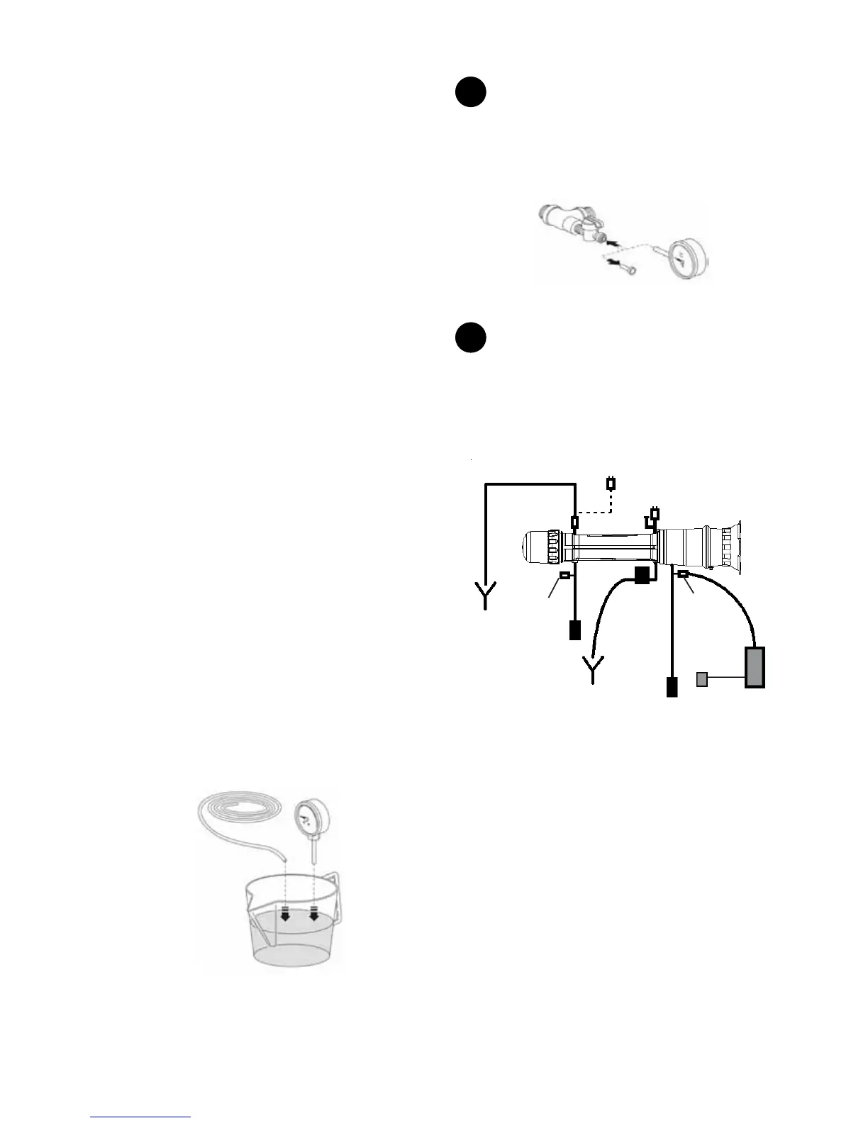
Place and soak the adaptor tip and the 1/4” tubing ends in
5-6% unscented household chlorine bleach (Clorox) for 5
minutes. The brass adaptor will tarnish with time but this is
acceptable. Do not submerge the entire pressure gauge into
the sanitizer as it may damage it’s internal components. See
Figure 66.
Figure 66
1
Close inlet and outlet valves. Use the controller to
initiate a manual ush sequence to bring the system pressure
to zero. Refer to the instructions in the Controller Functions
section on how to perform a manual ush sequence. Insert
pressure gauges into the inlet and outlet mini ball valves and
open the valves. Conrm that the system pressure is zero.
Figure 67
2
Remove the air relief valve near the system cap
(Figure 68) and replace it with the spare mini ball valve from
the installation kit. Insert 1/4" tubing into this mini ball valve,
direct this tubing to a drain or a pail. Open this mini ball valve.
Plug one end of the second 1/4" tubing into the outlet mini ball
valve and the other end into the integrity tester.
Inlet Mini
Ball
Valve
1/4”
tubing
Drain
Solenoid
Valve
Outlet
Mini Ball
Valve
Integrity
Te ster
Outlet
Valve
Inlet
Valve
Drain
1/4”
tubing
Drain
or pail
Air Vent
Assembly
Integrity
Te ster
Transformer
Remove
Air
Relief
Valve
Spare Mini
Ball Valve
Figure 68