43
5
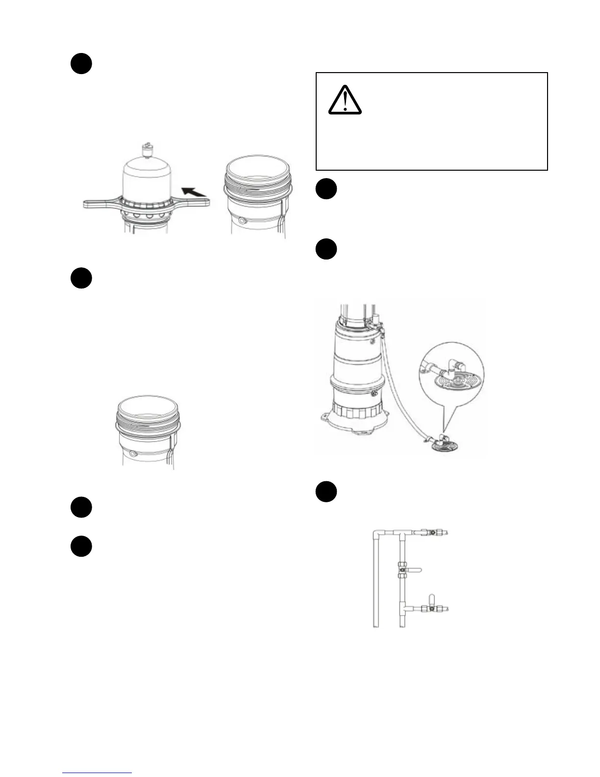
Remove the system cap and remove the prelter. If the
system is equipped with the carbon prelter, discard the
carbon prelter. If the system is equipped with the stainless
steel prelter, clean and set aside the stainless steel prelter
temporarily. The stainless steel prelter can be stored in the
system for the winter in step 7.
Open
Figure 75
6
Fill with approximately 3 US gal (12 liters) of -58°F (-50°C)
propylene glycol based plumbing antifreeze. The UFC 211 and
UF 211 series models do not have enough internal space to
accommodate 3 gallons of antifreeze initially. Remove the plug
from the outlet stainless steel ex hose and drain some
antifreeze/water mix from the system into an empty container.
Add the remainder of the antifreeze into the internal prelter
cavity. The uid level in the system must be at least 2” above
the bottom of the internal prelter cavity. Reinstall the plug
into the outlet stainless steel ex hose.
Antifreeze level at
least 2" from bottom
of Prelter cavity.
Figure 76
7
If a stainless steel prelter has been set aside, place the
stainless steel prelter in the prelter cavity.
8
For all systems, replace the system cap using the cap
wrench and check both plugs (drain and outlet) for any leaks.
The system is ready for winter.
Spring Start-Up Following Winterization
WARNING: Do NOT allow the
plumbing antifreeze/ water mix to drain onto the
ground, or into a septic bed, storm sewer or any body
of water. Check the plumbing antifreeze manufacturer’s
directions and warnings for more information.
1
Drain antifreeze solution from the system by removing
the outlet plug. Drain into proper containers. Dispose of the
antifreeze solution in accordance with the manufacturer’s
directions.
2
Remove drain plug from drain solenoid valve and
reconnect the elbow and piping. Ensure the drain is in
accordance with the initial set-up as described in the System
Installation section.
Drain hose must be
anchored down to
the oor or wall and
directed down into the
drain
The local
plumbing code
may require an
air gap to be
installed at the
drain line.
Figure 77
3
Open the inlet valve to ll the system with water. Air will
escape through the air relief valve in the system cap.
Inlet Valve
Bypass Valve
Outlet Valve
Figure 78