– 57 –
Selector Switch Removal
To remove the selector switches, remove the
selector switch knobs and lay the backsplash
assembly on its face. Then remove the rear panel.
Disconnect the J615 connector from the control.
Lift the tab on the selector switch and turn the
switch assembly counter clockwise to remove. Do
this for all of the option selector switches.
Diagnosing Selector Switches Using Service Mode
Diagnosing any of the option switches can be done
using the Service Mode Test 18.
16 + 2 = Test 18
Press the Start button to enter the test. Each option
NQRELVUHSUHVHQWHGE\DVSHFL¿FF\FOHVWDWXV/('
(Far left option knob to the far left cycle status LED)
When the knob position changes, the cycle status
LED will blink. With each click of the knob to the
right, the LED will blink faster. With each click to the
left, the LED will blink slower.
If a position on the switch is malfunctioning, the LED
will not blink, indicating the switch is bad.
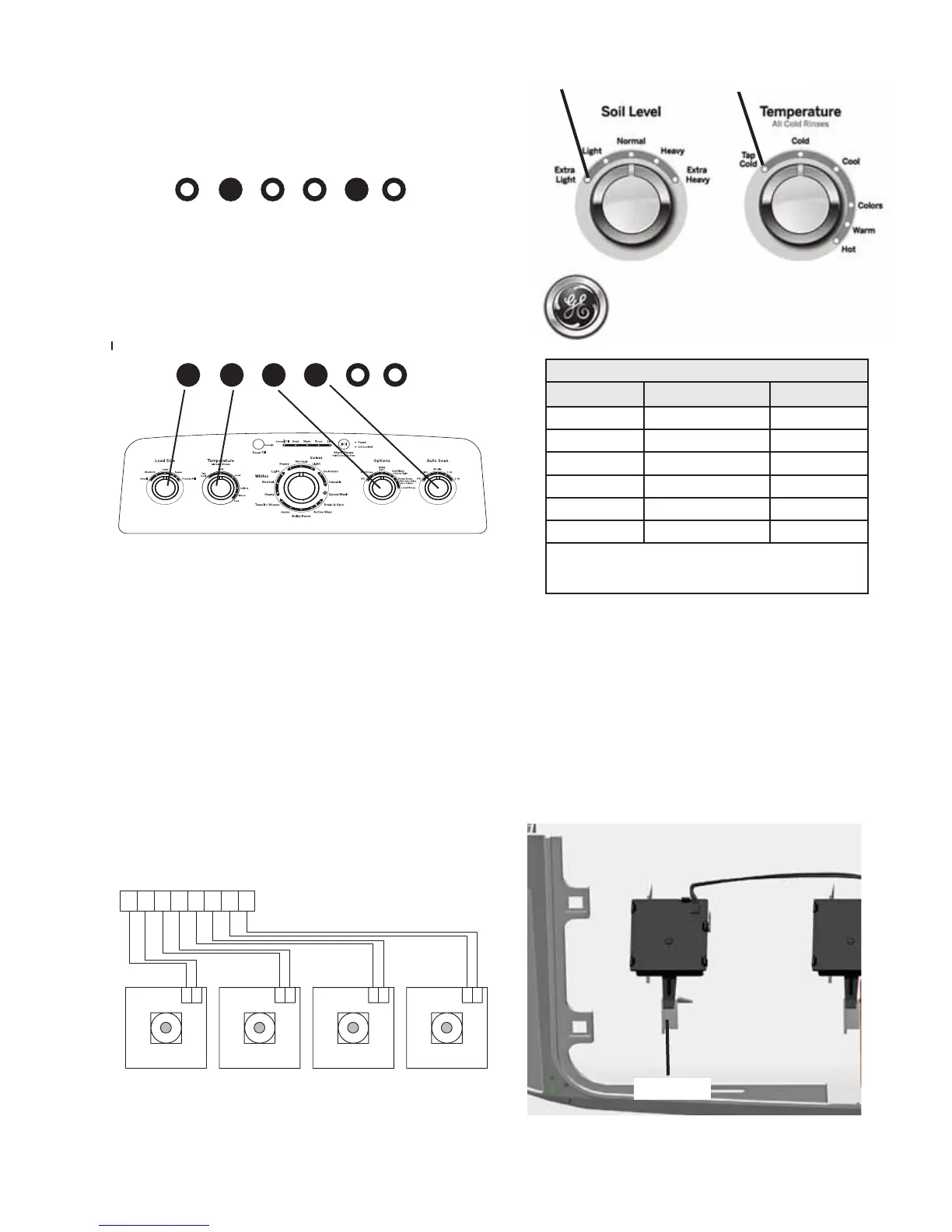
Diagnosing Selector Switches From the Control
The resistance and voltage of the switch being
tested can be read from the J615 connector on
the control board. Position 1 is to the far left on
the selector switch being tested. The further right
the switch is turned, the higher the resistance or
voltage.
32 16 8 4 2 1
1
8
1 1 1
1
J615
N-24
N-24
R-24
R-24
W-24
W-24
Y-24
Y-24
R-24
R-24
W-24
W-24
N-24
N-24
Y-24
Y-24
Lift Tab
Position 1
Knob 1
Position 1
Knob 2
Cycle Status LEDs
EC FF
Knob 1
Rotary Switch DC Voltage Resistance Table
Position
Resistance (k
)
Voltage
1
2
3
4
5
6
Position 1 is to the far left.
Turn towards the right to advance position.
 Loading...