EasyManua.ls Logo

GE IAC57A - Page 13

GE IAC57A
18 pages
Print Icon
To Next Page IconTo Next Page
To Previous Page IconTo Previous Page
Loading...
Time
Overcurrent
Relays
Type
IAC
GEH
-
1753
I
NO U CTIO N
\
UN
I T
v
iu
xu
TO
TIMER
"
STOP
"
TO
INDICATING
LIGHT
WHEN
CHECKING
PICKUP
OF
MAIN
UNIT
3
>
TO
INDICATING
LIGHT
WHEI
CHECKING
PICKUP
OF
INSTANTANEOUS
UNIT
SEAL
-
IN
UN
I
T
IN STA NT
.
UNI T
n
.
6
o
6
1 2 3 4 5
IN D UCTI ON
UN
|
T
O O O O
7
8
9
10
6
XLA
13
TEST
PLUG
A
IN STA NT
.
T
UN
I
T
VARIABLE
RESISTOR
\
TO
TIMER
"
START
"
v
*
V
Yr
~
^
•
3
5
9
y
.
y
.
V
*
v
f
•
1
1
TO
ACCURATELY
REPRODUCE
RELAY
CHARACTERISTICS
ALL
TESTS
SHOULD
BE
MADE
WITH
RELAY
IN
CASE
.
/
/
I
1
o
2
6
10
MIN
.
RECOMMENDED
VOLTS
,
120
AT
RATED
FREQUENCY
•
*
SH OR T
FI NGER
Fig
.
15
(
K
-
Fig
.
16
(
K
-
6154399
-
7
)
Testing
Connections
for
Type
IAC
Relays
such
as
Type
IAC
51
A
6209663
[
8
]
)
Internal
Connections
for
the
Type
IAC
52
B
Relay
(
Front
View
)
INSTALLATION
LOCATION
circuits
and
other
circuits
with
shorting
bars
that
the
auxiliary
brush
be
bent
high
enough
to
engage
the
connecting
plug
or
test
plug
before
the
main
brushes
do
.
This
will
prevent
CT
secondary
cir
-
cuits
from
being
opened
.
The
location
should
be
clean
and
dry
,
free
from
dust
and
excessive
vibration
,
and
well
lighted
to
facilitate
inspection
and
testing
.
MOUNTING
The
relay
should
be
mounted
on
a
vertical
surface
.
The
outline
and
panel
diagrams
are
shown
in
Figs
.
20
and
21
.
CONNECTING
PLUG
MAIN
BRUSH
CONNECTING
SLOCK
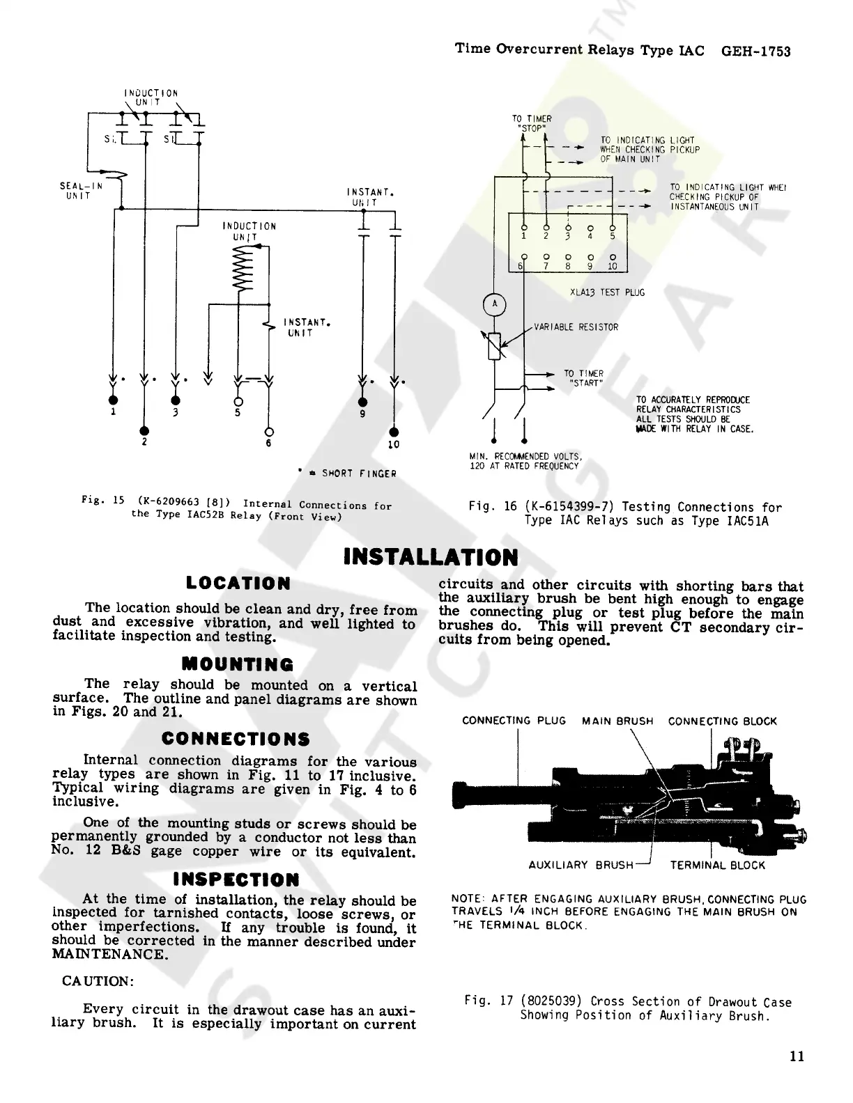
CONNECTIONS
Internal
connection
diagrams
for
the
various
relay
types
are
shown
in
Fig
.
11
to
17
inclusive
.
Typical
wiring
diagrams
are
given
in
Fig
.
4
to
6
inclusive
.
One
of
the
mounting
studs
or
screws
should
be
permanently
grounded
by
a
conductor
not
less
than
No
.
12
B
&
S
gage
copper
wire
or
its
equivalent
.
TERMINAL
BLOCK
AUXILIARY
BRUSH
INSPECTION
NOTE
:
AFTER
ENGAGING
AUXILIARY
BRUSH
,
CONNECTING
PLUG
TRAVELS
'
A
INCH
BEFORE
ENGAGING
THE
MAIN
BRUSH
ON
'
"
HE
TERMINAL
BLOCK
.
At
the
time
of
installation
,
the
relay
should
be
inspected
for
tarnished
contacts
,
loose
screws
,
or
other
imperfections
.
If
any
trouble
is
found
,
it
should
be
corrected
in
the
manner
described
under
MAINTENANCE
.
CAUTION
:
Fig
.
17
(
8025039
)
Cross
Section
of
Drawout
Case
Showing
Position
of
Auxiliary
Brush
.
Every
circuit
in
the
drawout
case
has
an
auxi
-
liary
brush
.
It
is
especially
important
on
current
11
Courtesy of NationalSwitchgear.com