All GE ranges are equipped
with an Anti-Tip device.
The installation of this
device is an important,
required step in the
installation of the range.
Specification Created 6/13
330446
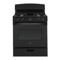
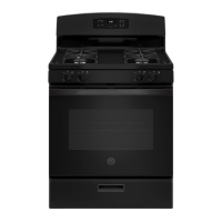
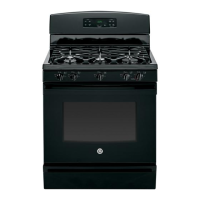
JGBS14PCFWW
GE
®
30" Free-Standing Gas Range
Dimensions and Installation Information (in inches)
Electrical Rating: 120V, 60Hz, 5A
Installation Information: Before installing, consult installation
instructions packed with product for current dimensional data.
For answers to your Monogram
®
or GE
®
appliance questions, visit our website at
geappliances.com or call GE Answer Center
®
service, 800.626.2000.
* ADA qualified based
on Uniform Federal
Accessibility Standards
Minimum to
cabinets on
either side
of the range.
Minimum
clearance
to left wall
Minimum
Minimum
clearance to
right wall
Maximum
depth for
cabinets above
countertops
To cabinets below cooktop
and at the range back
To cabinets
below
cooktop and
at the range
back
"
1"
30"
30"
13"
1"
36"
0"
Front edge of
the range side
panel forward
from cabinet
0"
1/4"
GAS PIPE AND ELECTRICAL
OUTLET LOCATIONS
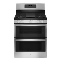
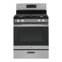
SINGLE OVEN GAS RANGE
Recommended area for 240V
outlet on rear wall and area for
through-the-wall conection of
pipe stub and shut-off valve.
Recommended area
for through-the-floor
connection of pipe stub
and shut-off valve.
4 1/2"
4"
2"
8"
5"
3"
14 1/2"
9"
30"
46 1/4"
28 3/4"
w/ handle
26 1/4"
w/o handle
30"
10 1/4"
36"
to
36 1/2"
Minimum to
cabinets on
either side
of the range.
Minimum
clearance
to left wall
Minimum
Minimum
clearance to
right wall
Maximum
depth for
cabinets above
countertops
To cabinets below cooktop
and at the range back
To cabinets
below
cooktop and
at the range
back
18"
1"
30"
30"
13"
1"
36"
0"
Front edge of
the range side
panel forward
from cabinet
0"
1/4"
GAS PIPE AND ELECTRICAL
OUTLET LOCATIONS
SINGLE OVEN GAS RANGE
Recommended area for 240V
outlet on rear wall and area for
through-the-wall conection of
pipe stub and shut-off valve.
Recommended area
for through-the-floor
connection of pipe stub
and shut-off valve.
4 1/2"
4"
2"
8"
5"
3"
14 1/2"
9"
30"
46 1/4"
28 3/4"
w/ handle
26 1/4"
w/o handle
30"
10 1/4"
36"
to
36 1/2"