STEP4
PROVIDEADEQUATEGASSUPPLY
This cooktop is designed to operate on natural gas
at 4"of water column pressure or on LP gas at 10"
ofwater column pressure. It is shipped from the
factory set for natural gas. If you decide to use
this cooktop with LP gas, conversion adjustments
must be made by a service technician or other
qualified person.
A pressure regulator is to be connected in series
with the manifold of the cooktop and must
remain in series with the supply line regardless
ofwhether natural or LP gas is being used.
For proper operation, the maximum inlet
pressure to the regulator must be no more
than 10" water column pressure for natural
gas, or 14" water column pressure for LP
gas. For checking the regulator, the inlet
pressure must be at least 1" greater than the
regulator output setting. If the regulator is set
for 4"of water column pressure, the inlet
pressure must be at least 5". If the regulator is
set for 10", the inlet pressure must be at least 11".
For ease of installation, and if local codes permit,
the gas supply line into the cooktop should be
1/2" or 3/4" I.D. flexible metal appliance
connector three to five feet in length.
STEP5
PREPAREFORDUCTWORK
NOTE: Ductwork MUST be vented outside.
DO NOT vent into a wall, ceiling, crawlspace,
attic or any concealed space.
Determine the best route for ductwork;
it can be routed in a variety of ways, depending
on the kitchen layout.
Throu_ 'h wall to roof
Direct to rear wall
Directly through wall
Between floor joists
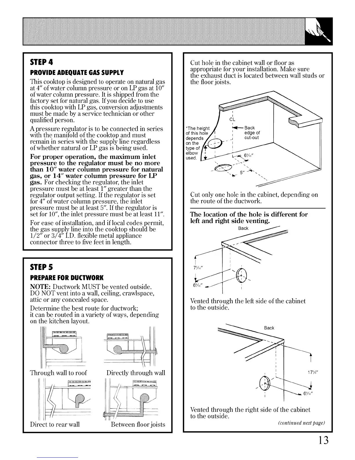
Cut hole in the cabinet wall or floor as
appropriate for your installation. Make sure
the exhaust duct is located between wall studs or
the floor joists.
Cut only one hole in the cabinet, depending on
the route of the ductwork.
The location of the hole is different for
left and right side venting.
Back
7_o"
Vented through the left side of the cabinet
to the outside.
Back
Vented through the right side of the cabinet
to the outside.
(continued next page)
13