Models JV332, JV346
Model JV346 ducted installation: Remove the charcoal
pad from the filter. Remove the baffle from the top of the
hood. Re-install the baffle so the short side marked
“VENTED’ is visable. The long side of the baffle should
be inside the hood.
The hood has been designed to mate with a standard 3!4”
x 10“rectangular or 7“ diameter round duct.
Rectangular Duct See Fig. 5,6 & 10: The exhaust outlet
can be installed as either the top or rear by removing the
desired rectangular knockout. A rectangular damper is
supplied with the hood.
Round Duct See Fig. 4 &9: If round duct is desired
either of the following methods must be used:
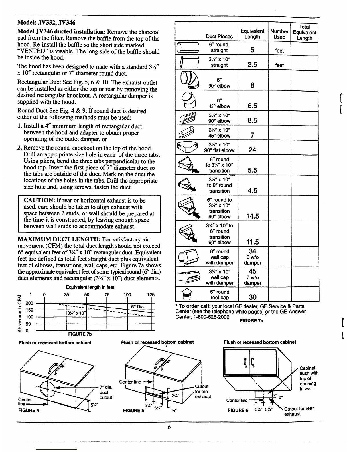
Total
Equivalent
Length
=4=
Duct Pieces
~ 6 round,
~ straight
D
3%” x 10”
straight
Q)
6“
90° elbow
@
6
45° elbow
8
I
6.5 I
G!@
3X” x 10”
90° elbow
8.5
I
1.
2.
Install a 4“ minimum length of rectangular duct
between the hood and adapter to obtain proper
operating of the outlet damper, or
Remove the round knockout on the ton of the hood.
3W’X1O”
45° elbow
7
I
63
3X” x 10”
90° flat elbow
m
I
--i-
Drill an appropriate size hole in each ‘ofthe three tabs.
a
6“ round
to 3%” x 1
o“
transition
Using pliers, bend the three tabs perpendicular to the
hood top. Insert the first piece of 7“ diameter duct so
the tabs are outside of the duct. Mark on the duct the
locations of the holes in the tabs. Drill the appropriate
size hole and, using screws, fasten the duct.
%
3%” x 1o“
to
6“ round
transition
4.5 I
CAUTION: If rear or horizontal exhaust is to be
used, care should be taken to align exhaust with
space between 2 studs, or wall should be prepared at
the time it is constructed, by leaving enough space
between wall studs to accommodate exhaust.
MAXIMUM DUCT LENGTH: For satisfactory air
%
6“ round to
3%” x 1
o“
transition
90° elbow
T
14.5
11.5
%
3X” x 1o“to
6“ round
transition
900 elbow
movement (CFM) the total duct length should not exceed
65 equivalent feet of 3%’x 10”rectangular duct. Equivalent
feet are defined as total feet straight duct plus equivalent
feet of elbows, transitions, wall caps, etc. Figure 7a shows
theapproximateequivalentfeetof some typicalround (6”dia)
duct elements and rectangular (3%”x 10”) duct elements.
Equivalentlengthin feet
34
6 W/O
damper
@
6 round
wall cap
with damper
4-
45
7 Wlo
damper
@
3%” x 1o“
wall cap
with damper
@
6“ round
roof cap
3J0
25 50 75 100
125
b 200
--
------
6“
Dia.
:
150
----
7
3!4” x 1o“
------
~ 100
------
w -
9 50
30
I
*To order call: your local GE dealer, GE Service & Parts
Center (see the telephone white Daaes) or the GE Answer
Center,”1-800-626-2000. ‘ “ ‘”
FIGURE 7a
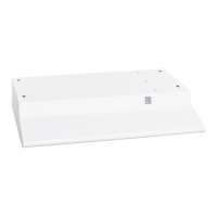
Flush or recessed bottom cabinet
Flush or recessed bottom cabinet
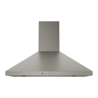
Flush or recessed bottom cabinet
Center
line -
Cabinet
flush with
top of
opening
in wall.
W:;ss’
FIGURE 5
?4”
7mdia.
duct
cutout
FIGURE6 5~” 5X”
X C@out
for rear
exhaust