3. POWER SUPPLY
A! CIRW~ VOLTAGE: This hood must be connected
to a SUPPIYcircuit of the proper voltage and frequency
~~
as sPecified on the rating @ate. Wire size must
“}
.,,
.-_
conform to the requirements of the National Electrical
Code or the prevailing local code for hoods of this -
‘sting” The rating plate is located on the rear wall
of the hood.
B. FUSE RATING: 15
anlPS.
c.
?
1
D.
.
unless otherwise specified by local codes, bring
a 15amp 2 wire circuit with ground to the area of
t
the power supply connection box.
USE OF OPTIONAL TOP POWER SUPPLM
l“hepower supply can be attached through the top
knockout if desired, but only the top or back knockout
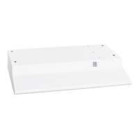
shall be opened (See Figs. 8,9 and 10).
Exhaustoutietconnects to 3x” x 10“ rectangular duct outlet has TOTAL
ADJUSTMENT of 1%“from side to side to simplify duct alignment.
NOTE: Exhaust outiet can
be installed as either TOP
or REAR by removing
desired knockout. Insert a
screw driver under edge of
knockout. Break tabs and
1//
remove knockout with pliers.
-.
Power supply
entrance openings
,
in
top and rear of hood.
NOTE: Use of REAR opening
T
is recommended
FIGURE 10
Centerfine of hood
Power
Supply entrance
openings in
top
7??”~
and rear of hood.
NOTE: Use of REAR opening
is recommended.
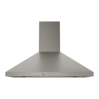
FIGURE 8
Exhaust outlet connects to 7“ dia. duct,
Al.
Centerline of hood
Center
line
NOTE: Use of REAR
v
1
y,”--l
opening is recommended.
FIGURE 9
4. HOOD INSTALLATION
A. MECHANICAL
NOTE: When possible, it is more convenient to mount
and wire the hood before the base cabinet is put in date.
1. Take out 1 screw and remove the power
SUppl~
connection box cover located on the underside
of the hood (See Fig. 13 Model: JV322) (See Fig. 12
Models: JN322, JV332 &JV346).
1
2. To locate the 4 mounting holes, position the hood
)
carefully against the bottom of the wall cabinet and
mark the screw positions through the keyhole slots in
the hood. Drill 3/32” pilot holes for the mounting
FIGURE 11
screws
in the small end of the keyhole.
Direction of
3.
-+.
.
movement for mounting
%rtially drive the 4 mounting screws so that the
heads of the screws extend 1/2” below the bottom of
the cabinet. Raise the hood against the bottom of the
cabinet, making sure that the heads of the mounting
screws protrude through the hole section of the
keyhole slots as shown in Fig. 11. Before tightening
the mounting screws, attach the power supply cable
to the hood. Then push the hood back against the
wall and tighten the mounting screws.
●
7