– 16 –
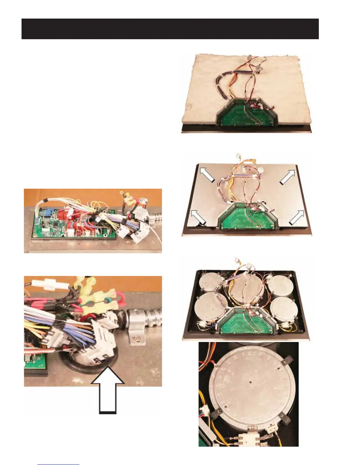
Accessing Electronic Control Cooktop Elements
1. Disconnect power to the cooktop.
2. Carefully remove the cooktop from the
installation and lay the glass side down on a
protected surface.
3. Remove the T20 screws from the perimeter.
4. Remove four 1/4 in. hex head screws from the
power supply cover.
5. Disconnect two harness connectors from the
power supply board and one from the RJ45
connector. Set the assembly aside.
6. 5HPRYH¿YHLQKH[KHDGVFUHZVIURPWKH
relay board cover.
7. Disconnect the three multi-pin connectors and
both sets of L1 and L2 wires.
8. Remove the bottom cover and feed the
harnesses through the grommet.
9. Remove the bottom cover and place back into
the installation opening.
10. Remove the insulation.
11. Remove four 1/4 in. hex head screws from the
insulation cover.
12. Note that spring clips secure elements onto
maintop glass and frame assembly.
Grommet
 Loading...