7
Installation Instructions
Electrical Connections
C
C1
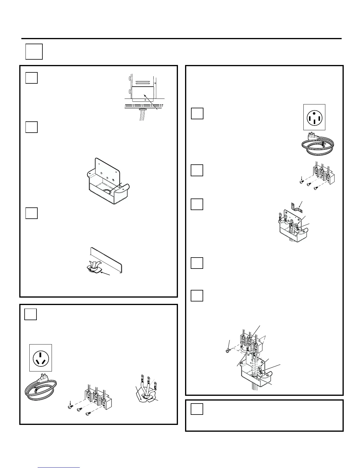
Remove wire cover at
lower rear of range.
WIRE COVER
C2
When using a power cord, remove the
knockout in the connection plate with
pliers as required by the size of the
strain relief or clamp supplied with cord.
Knockout
Terminal
Housing
C3
Insert power cord through hole in the
terminal housing, engage and tighten
strain relief clamp, leaving enough wire
length to attach terminals to terminal
block.
C3a
Connection
Plate
Strain
Relief
Clamp
3 wire
cord kit
FOLLOW INSTRUCTIONS BELOW IF
YOUR CORD IS 3 WIRE.
The power cord center wire must
be connected to middle terminal
on block. Attach remaining wires
securely. Do not remove ground
strap
C5
Re-install the wire cover making sure
the wires do not become pinched
between wire cover and housing.
50 Amp 4 Wire
C4a
Follow instructions
below if your cord is 4
wire.
C4b
Remove the screws on
the terminal block. Do
not remove terminal
block.
Remove
3 screws
REMOVE & DISCARD
GROUND STRAP
GROUND
WIRE
REUSE
GROUND WASHER
& GROUND SCREW
C4c
Remove the
green ground
screw. Then
remove the
ground strap and
discard it.
Terminal Block
C4d
Attach the green or bare wire below the
terminal block with the green ground
screw and washer that were removed
earlier.
C4e
Connect the red and black wires to the
outside terminals. The white wire must be
connected to the center terminal.
OR
Remove
3 screws
Black
White
Red
3-Screws
Grounded
Neutral
Terminal
Center
Wire
(white)
Ground
Wire
Strain
Relief
Clamp
Ground Screw
& Washer
Black
White
Red
50 Amp 3 Wire
NEW CONSTRUCTION AND FOUR
CONDUCTOR BRANCH CIRCUIT
Strain
Relief
Clamp
 Loading...